Product Description
Product Description
Custom Aluminum 6061 Turning Part Precision Steel CNC Fabrication sheet metal stamping Machining Parts
1. Product Details:
Material: bronze, brass, copper, aluminum, steel, stainless steel, hardend metal
Technology: CNC machining, Welding pressed
Surface treatment: sand blast, polishing, painting, powder coating
Machining: grinding, tapping, drilling, cnc machining,Laser cutting
Application: constructional equipment, machinery
2. CNC Machining
| Material | Aluminum,Stainless steel, Brass, Copper, Carbon steel, Plastic (POM,PVC,PEEK,PU etc) |
| Surface treatment | Anodized, Passivation, heat treatment, painting, Power coating, Black Oxide, Silver/Gold plating |
| Application Industry | Aerospace, Automotive, Medical, telecommunications, electronic, |
| Sensors, Optical instruments, computers,Motorcycles etc. | |
| Processing method | CNC machining, CNC turning, 3/4/5 axis CNC milling, wire-cutting, EDM, grinding. |
|
Drilling, Tapping, welding, bending,die casting, stamping and etc. |
| Precision of workpiece: | +/-0.005~+/-0.002mm | ||
| Roughness of workpiece: | Ra≤0.1 | ||
3.QC Inspection
Inspection Euqipment:
We have the chemical elements analysis centre and the mechanical testing centre
which include the following quality control measures:
Spectrographic analysis, magnaflux crack detection, ultrasonic detection, dynamic fatigue testing, hardness testing, proof and ultimate breaking strength test… TUV DIN EN ISO 9001: 2000 & ISO/TS16949 available
In order to ensure the quality of the orders,
our independent QC members to carry out strict inspection at each stage:
(1)Incoming material inspection
(2)Inspection of work-in-progress
(3)Finished product inspection
(4)Random warehouse inspections
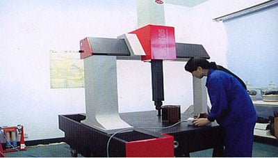
All of our operations are strictly compliant with ISO 9001: 2008 guidelines We own automated casting lines, CNC machining, CMM inspection, spectrometers and MT testing equipment, X-ray. To benefit from our strong OEM/ODM capabilities and considerate services, contact us today. We will sincerely create and share success with all clients.
| After-sales Service: | Yes |
|---|---|
| Warranty: | 12 |
| Condition: | New |
| Certification: | ISO9001 |
| Standard: | DIN |
| Customized: | Customized |
| Samples: |
US$ 1/Piece
1 Piece(Min.Order) | |
|---|
| Customization: |
Available
| Customized Request |
|---|

Benefits and Uses of Miter Gears
If you’ve ever looked into the differences between miter gears, you’re probably wondering how to choose between a Straight toothed and Hypoid one. Before you decide, however, make sure you know about backlash and what it means. Backlash is the difference between the addendum and dedendum, and it prevents jamming of the gears, protects the mating gear surfaces, and allows for thermal expansion during operation.
Spiral bevel gears
Spiral bevel gears are designed to increase efficiency and reduce cost. The spiral shape creates a profile in which the teeth are cut with a slight curve along their length, making them an excellent choice for heavy-duty applications. Spiral bevel gears are also hypoid gears, with no offsets. Their smaller size means that they are more compact than other types of right-angle gears, and they are much quieter than other types of gear.
Spiral bevel gears feature helical teeth arranged in a 90-degree angle. The design features a slight curve to the teeth, which reduces backlash while increasing flexibility. Because they have no offsets, they won’t slip during operation. Spiral bevel gears also have less backlash, making them an excellent choice for high-speed applications. They are also carefully spaced to distribute lubricant over a larger area. They are also very accurate and have a locknut design that prevents them from moving out of alignment.
In addition to the geometric design of bevel gears, CZPT can produce 3D models of spiral bevel gears. This software has gained widespread attention from many companies around the world. In fact, CZPT, a major manufacturer of 5-axis milling machines, recently machined a prototype using a spiral bevel gear model. These results prove that spiral bevel gears can be used in a variety of applications, ranging from precision machining to industrial automation.
Spiral bevel gears are also commonly known as hypoid gears. Hypoid gears differ from spiral bevel gears in that their pitch surface is not at the center of the meshing gear. The benefit of this gear design is that it can handle large loads while maintaining its unique features. They also produce less heat than their bevel counterparts, which can affect the efficiency of nearby components.
Straight toothed miter gears
Miter gears are bevel gears that have a pitch angle of 90 degrees. Their gear ratio is 1:1. Miter gears come in straight and spiral tooth varieties and are available in both commercial and high precision grades. They are a versatile tool for any mechanical application. Below are some benefits and uses of miter gears. A simple explanation of the basic principle of this gear type is given. Read on for more details.
When selecting a miter gear, it is important to choose the right material. Hard faced, high carbon steel is appropriate for applications requiring high load, while nylon and injection molding resins are suitable for lower loads. If a particular gear becomes damaged, it’s advisable to replace the entire set, as they are closely linked in shape. The same goes for spiral-cut miter gears. These geared products should be replaced together for proper operation.
Straight bevel gears are the easiest to manufacture. The earliest method was using an indexing head on a planer. Modern manufacturing methods, such as the Revacycle and Coniflex systems, made the process more efficient. CZPT utilizes these newer manufacturing methods and patented them. However, the traditional straight bevel is still the most common and widely used type. It is the simplest to manufacture and is the cheapest type.
SDP/Si is a popular supplier of high-precision gears. The company produces custom miter gears, as well as standard bevel gears. They also offer black oxide and ground bore and tooth surfaces. These gears can be used for many industrial and mechanical applications. They are available in moderate quantities from stock and in partial sizes upon request. There are also different sizes available for specialized applications.
Hypoid bevel gears
The advantages of using Hypoid bevel and helical gears are obvious. Their high speed, low noise, and long life make them ideal for use in motor vehicles. This type of gear is also becoming increasingly popular in the power transmission and motion control industries. Compared to standard bevel and helical gears, they have a higher capacity for torque and can handle high loads with less noise.
Geometrical dimensioning of bevel/hypoid bevel gears is essential to meet ANSI/AGMA/ISO standards. This article examines a few ways to dimension hypoid bevel and helical gears. First, it discusses the limitations of the common datum surface when dimensioning bevel/helical gear pairs. A straight line can’t be parallel to the flanks of both the gear and the pinion, which is necessary to determine “normal backlash.”
Second, hypoid and helical gears have the same angular pitch, which makes the manufacturing process easier. Hypoid bevel gears are usually made of two gears with equal angular pitches. Then, they are assembled to match one another. This reduces noise and vibration, and increases power density. It is recommended to follow the standard and avoid using gears that have mismatched angular pitches.
Third, hypoid and helical gears differ in the shape of the teeth. They are different from standard gears because the teeth are more elongated. They are similar in appearance to spiral bevel gears and worm gears, but differ in geometry. While helical gears are symmetrical, hypoid bevel gears are non-conical. As a result, they can produce higher gear ratios and torque.
Crown bevel gears
The geometrical design of bevel gears is extremely complex. The relative contact position and flank form deviations affect both the paired gear geometry and the tooth bearing. In addition, paired gears are also subject to process-linked deviations that affect the tooth bearing and backlash. These characteristics require the use of narrow tolerance fields to avoid quality issues and production costs. The relative position of a miter gear depends on the operating parameters, such as the load and speed.
When selecting a crown bevel gear for a miter-gear system, it is important to choose one with the right tooth shape. The teeth of a crown-bevel gear can differ greatly in shape. The radial pitch and diametral pitch cone angles are the most common. The tooth cone angle, or “zerol” angle, is the other important parameter. Crown bevel gears have a wide range of tooth pitches, from flat to spiral.
Crown bevel gears for miter gear are made of high-quality materials. In addition to metal, they can be made of plastic or pre-hardened alloys. The latter are preferred as the material is less expensive and more flexible than steel. Furthermore, crown bevel gears for miter gears are extremely durable, and can withstand extreme conditions. They are often used to replace existing gears that are damaged or worn.
When selecting a crown bevel gear for a miter gear, it is important to know how they relate to each other. This is because the crown bevel gears have a 1:1 speed ratio with a pinion. The same is true for miter gears. When comparing crown bevel gears for miter gears, be sure to understand the radii of the pinion and the ring on the pinion.
Shaft angle requirements for miter gears
Miter gears are used to transmit motion between intersecting shafts at a right angle. Their tooth profile is shaped like the mitre hat worn by a Catholic bishop. Their pitch and number of teeth are also identical. Shaft angle requirements vary depending on the type of application. If the application is for power transmission, miter gears are often used in a differential arrangement. If you’re installing miter gears for power transmission, you should know the mounting angle requirements.
Shaft angle requirements for miter gears vary by design. The most common arrangement is perpendicular, but the axes can be angled to almost any angle. Miter gears are also known for their high precision and high strength. Their helix angles are less than ten degrees. Because the shaft angle requirements for miter gears vary, you should know which type of shaft angle you require before ordering.
To determine the right pitch cone angle, first determine the shaft of the gear you’re designing. This angle is called the pitch cone angle. The angle should be at least 90 degrees for the gear and the pinion. The shaft bearings must also be capable of bearing significant forces. Miter gears must be supported by bearings that can withstand significant forces. Shaft angle requirements for miter gears vary from application to application.
For industrial use, miter gears are usually made of plain carbon steel or alloy steel. Some materials are more durable than others and can withstand higher speeds. For commercial use, noise limitations may be important. The gears may be exposed to harsh environments or heavy machine loads. Some types of gears function with teeth missing. But be sure to know the shaft angle requirements for miter gears before you order one.


editor by CX 2023-05-19
China OEM Gtig Customized Rotary Oil Drilling Rig Gear for Industrial Machinery supplier
Product Description
Product Description
| Modulo | Above 0.8 |
| Numero di Denti | Above 9teeth |
| Angolo d’Elica Helix Angle | Up to 45 |
| bore diameter | Above 6mm |
| axial length | Above 9mm |
| Gear model | Customized gear accoding to customers sample or drawing |
| Processing machine | CNC machine |
| Material | 20CrMnTi/ 20CrMnMo/ 42CrMo/ 45#steel/ 40Cr/ 20CrNi2MoA/304 stainless steel |
| Heat treattment | Carburizing and quenching/ Tempering/ Nitriding/ Carbonitriding/ Induction hardening |
| Hardness | 35-64HRC |
| Qaulity standerd | GB/ DIN/ JIS/ AGMA |
| Accuracy class | 5-8 class |
| Shipping | Sea shipping/ Air shipping/ Express |
Company Profile
| Application: | Motor, Electric Cars, Motorcycle, Machinery, Car |
|---|---|
| Hardness: | Soft Tooth Surface |
| Gear Position: | Internal Gear |
| Manufacturing Method: | Rolling Gear |
| Toothed Portion Shape: | Spur Gear |
| Material: | Stainless Steel |
| Samples: |
US$ 500/Piece
1 Piece(Min.Order) | |
|---|

Types of Miter Gears
The different types of miter gears include Hypoid, Crown, and Spiral. To learn more, read on. In addition, you’ll learn about their differences and similarities. This article will provide an overview of the different types of miter gears. You can also choose the type that fits your needs by using the guide below. After you’ve read it, you’ll know how to use them in your project. You’ll also learn how to pair them up by hand, which is particularly useful if you’re working on a mechanical component.
Bevel gears
Bevel and miter gears are both used to connect two shafts that have different axes. In most cases, these gears are used at right angles. The pitch cone of a bevel gear has the same shape as that of a spur gear, except the tooth profile is slightly tapered and has variable depth. The pinions of a bevel gear are normally straight, but can be curved or skew-shaped. They can also have an offset crown wheel with straight teeth relative to the axis.
In addition to their industrial applications, miter gears are found in agriculture, bottling, printing, and various industrial sectors. They are used in coal mining, oil exploration, and chemical processes. They are an important part of conveyors, elevators, kilns, and more. In fact, miter gears are often used in machine tools, like forklifts and jigsaws.
When considering which gear is right for a certain application, you’ll need to think about the application and the design goals. For example, you’ll want to know the maximum load that the gear can carry. You can use computer simulation programs to determine the exact torque required for a specific application. Miter gears are bevel gears that are geared on a single axis, not two.
To calculate the torque required for a particular application, you’ll need to know the MA of each bevel gear. Fortunately, you can now do so with CZPT. With the help of this software, you can generate 3D models of spiral bevel gears. Once you’ve created your model, you can then machine it. This can make your job much easier! And it’s fun!
In terms of manufacturing, straight bevel gears are the easiest to produce. The earliest method for this type of gear is a planer with an indexing head. Since the development of CNC machining, however, more effective manufacturing methods have been developed. These include CZPT, Revacycle, and Coniflex systems. The CZPT uses the Revacycle system. You can also use a CNC mill to manufacture spiral bevel gears.
Hypoid bevel gears
When it comes to designing hypoid bevel gears for miter and other kinds of gears, there are several important parameters to consider. In order to produce high-quality gearings, the mounting distance between the gear teeth and the pinion must be within a predefined tolerance range. In other words, the mounting distance between the gear teeth and pinion must be 0.05 mm or less.
To make this possible, the hypoid bevel gearset mesh is designed to involve sliding action. The result is a quiet transmission. It also means that higher speeds are possible without increasing noise levels. In comparison, bevel gears tend to be noisy at high speeds. For these reasons, the hypoid gearset is the most efficient way to build miter gears. However, it’s important to keep in mind that hypoid gears are not for every application.
Hypoid bevel gears are analogous to spiral bevels, but they don’t have intersecting axes. Because of this, they can produce larger pinions with smooth engagement. Crown bevel gears, on the other hand, have a 90-degree pitch and parallel teeth. Their geometry and pitch is unique, and they have particular geometrical properties. There are different ways to express pitch. The diametral pitch is the number of teeth, while circumferential measurement is called the circumference.
The face-milling method is another technique used for the manufacture of hypoid and spiral bevel gears. Face-milling allows gears to be ground for high accuracy and surface finish. It also allows for the elimination of heat treatment and facilitates the creation of predesigned ease-off topographies. Face-milling increases mechanical resistance by as much as 20%. It also reduces noise levels.
The ANSI/AGMA/ISO standards for geometric dimensioning differ from the best practices for manufacturing hypoid and bevel gears. The violation of common datum surfaces leads to a number of geometrical dimensioning issues. Moreover, hypoid gears need to be designed to incorporate the base pitches of the mating pinion and the hypoid bevel gear. This is not possible without knowing the base pitch of the gear and the mating pinion.
Crown bevel gears
When choosing crown bevels for a miter gear, you will need to consider a number of factors. Specifically, you will need to know the ratio of the tooth load to the bevel gear pitch radius. This will help you choose a bevel gear that possesses the right amount of excitation and load capacity. Crown bevels are also known as helical gears, which are a combination of two bevel gear types.
These bevel gears differ from spiral bevels because the bevels are not intersected. This gives you the flexibility of using a larger pinion and smoother engagement. Crown bevel gears are also named for their different tooth portions: the toe, or the part of the gear closest to the bore, and the heel, or the outermost diameter. The tooth height is smaller at the toe than it is at the heel, but the height of the gear is the same at both places.
Crown bevel gears are cylindrical, with teeth that are angled at an angle. They have a 1:1 gear ratio and are used for miter gears and spur gears. Crown bevel gears have a tooth profile that is the same as spur gears but is slightly narrower at the tip, giving them superior quietness. Crown bevel gears for miter gears can be made with an offset pinion.
There are many other options available when choosing a Crown bevel gear for miter gears. The material used for the gears can vary from plastics to pre-hardened alloys. If you are concerned with the material’s strength, you can choose a pre-hardened alloy with a 32-35 Rc hardness. This alloy also has the advantage of being more durable than plastic. In addition to being stronger, crown bevel gears are also easier to lubricate.
Crown bevel gears for miter gears are similar to spiral bevels. However, they have a hyperbolic, not conical, pitch surface. The pinion is often offset above or below the center of the gear, which allows for a larger diameter. Crown bevel gears for miter gears are typically larger than hypoid gears. The hypoid gear is commonly used in automobile rear axles. They are useful when the angle of rotation is 90 degrees. And they can be used for 1:1 ratios.
Spiral miter gears
Spiral bevel gears are produced by machining the face surface of the teeth. The process follows the Hertz theory of elastic contact, where the dislocations are equivalent to small significant dimensions of the contact area and the relative radii of curvature. This method assumes that the surfaces are parallel and that the strains are small. Moreover, it can reduce noise. This makes spiral bevel gears an ideal choice for high-speed applications.
The precision machining of CZPT spiral miter gears reduces backlash. They feature adjustable locking nuts that can precisely adjust the spacing between the gear teeth. The result is reduced backlash and maximum drive life. In addition, these gears are flexible enough to accommodate design changes late in the production process, reducing risk for OEMs and increasing efficiency and productivity. The advantages of spiral miter gears are outlined below.
Spiral bevel gears also have many advantages. The most obvious of these advantages is that they have large-diameter shafts. The larger shaft size allows for a larger diameter gear, but this means a larger gear housing. In turn, this reduces ground clearance, interior space, and weight. It also makes the drive axle gear larger, which reduces ground clearance and interior space. Spiral bevel gears are more efficient than spiral bevel gears, but it may be harder to find the right size for your application.
Another benefit of spiral miter gears is their small size. For the same amount of power, a spiral miter gear is smaller than a straight cut miter gear. Moreover, spiral bevel gears are less likely to bend or pit. They also have higher precision properties. They are suitable for secondary operations. Spiral miter gears are more durable than straight cut ones and can operate at higher speeds.
A key feature of spiral miter gears is their ability to resist wear and tear. Because they are constantly being deformed, they tend to crack in a way that increases their wear and tear. The result is a harder gear with a more contoured grain flow. But it is possible to restore the quality of your gear through proper maintenance. If you have a machine, it would be in your best interest to replace worn parts if they aren’t functioning as they should.
editor by CX 2023-05-15
China manufacturer Transmission Belt Gearbox Parts Conveyor Mining Machinery DIN8187 Driving Chains Specification Standard Chain Sprockets Single Wheel Spur Gear bevel spiral gear
Product Description
SPROCKET 1/2” X 5/16” 08B Sequence SPROCKETS
| For Chain Acc.to DIN8187 ISO/R 606 | |||||
| Tooth Radius r3 | thirteen.0mm | ||||
| Radius Width C | one.3mm | ||||
| Tooth Width b1 | 7.0mm | ||||
| Tooth Width B1 | seven.2mm | ||||
| Tooth Width B2 | 21.0mm | ||||
| Tooth Width B3 | 34.9mm | ||||
| 08B Collection ROLLER CHAINS | |||||
| Pitch | 12.7 mm | ||||
| Internal Width | seven.75 mm | ||||
| Roller Diameter | 8.fifty one mm | ||||
| Z | de | dp | SIMPLEX | DUPLEX | TRIPLEX |
| D1 | D2 | D3 | |||
| 8 | 37.2 | 33.18 | 8 | ten | ten |
| 9 | forty one.0 | 37.13 | eight | 10 | ten |
| ten | forty five.2 | 41.10 | 8 | ten | 10 |
| 11 | 48.7 | forty five.07 | ten | 10 | 12 |
| twelve | 53.0 | forty nine.07 | 10 | 10 | 12 |
| thirteen | fifty seven.4 | fifty three.06 | 10 | 10 | 12 |
| 14 | 61.8 | fifty seven.07 | ten | ten | twelve |
| fifteen | 65.5 | 61.09 | 10 | 10 | 12 |
| sixteen | sixty nine.5 | 65.10 | 10 | 12 | 16 |
| seventeen | seventy three.6 | sixty nine.11 | 10 | twelve | 16 |
| 18 | 77.8 | seventy three.14 | 10 | 12 | 16 |
| 19 | eighty one.7 | seventy seven.16 | ten | twelve | 16 |
| 20 | 85.8 | eighty one.19 | ten | twelve | 16 |
| 21 | 89.7 | 85.22 | twelve | 16 | sixteen |
| 22 | ninety three.8 | 89.24 | twelve | sixteen | sixteen |
| 23 | 98.2 | 93.27 | twelve | 16 | sixteen |
| 24 | a hundred and one.8 | 97.29 | 12 | sixteen | sixteen |
| 25 | a hundred and five.8 | one zero one.33 | 12 | 16 | sixteen |
| 26 | one hundred ten.0 | a hundred and five.36 | 16 | 16 | 16 |
| 27 | 114.0 | 109.40 | sixteen | sixteen | sixteen |
| 28 | 118.0 | 113.42 | 16 | sixteen | sixteen |
| 29 | 122.0 | 117.46 | sixteen | 16 | 16 |
| 30 | 126.1 | 121.50 | sixteen | sixteen | 16 |
| 31 | one hundred thirty.2 | 125.54 | sixteen | sixteen | 20 |
| 32 | 134.3 | 129.56 | 16 | 16 | 20 |
| 33 | 138.4 | 133.60 | sixteen | 16 | 20 |
| 34 | 142.6 | 137.64 | sixteen | sixteen | twenty |
| 35 | 146.7 | 141.68 | 16 | sixteen | 20 |
| 36 | 151.0 | a hundred forty five.72 | sixteen | twenty | twenty |
| 37 | 154.6 | 149.76 | 16 | twenty | twenty |
| 38 | 158.6 | 153.80 | sixteen | 20 | 20 |
| 39 | 162.7 | 157.83 | sixteen | 20 | twenty |
| 40 | 166.8 | 161.87 | 16 | twenty | 20 |
| 41 | 171.4 | 165.91 | 20 | twenty | twenty five |
| 42 | 175.4 | 169.94 | 20 | twenty | twenty five |
| forty three | 179.7 | 173.98 | 20 | 20 | 25 |
| forty four | 183.8 | 178.02 | twenty | twenty | twenty five |
| forty five | 188.0 | 182.07 | 20 | 20 | twenty five |
| 46 | 192.1 | 186.10 | twenty | twenty | twenty five |
| forty seven | 196.2 | 190.14 | twenty | 20 | twenty five |
| forty eight | 200.3 | 194.18 | 20 | 20 | 25 |
| 49 | 204.3 | 198.22 | 20 | twenty | 25 |
| 50 | 208.3 | 202.26 | 20 | twenty | twenty five |
| fifty one | 212.1 | 206.30 | 20 | twenty five | twenty five |
| fifty two | 216.1 | 210.34 | 20 | twenty five | twenty five |
| fifty three | 220.2 | 214.37 | twenty | twenty five | 25 |
| 54 | 224.1 | 218.43 | twenty | twenty five | twenty five |
| fifty five | 228.1 | 222.46 | twenty | twenty five | twenty five |
| fifty six | 232.2 | 226.50 | 20 | 25 | twenty five |
| 57 | 236.4 | 230.54 | twenty | 25 | twenty five |
| fifty eight | 240.5 | 234.58 | twenty | 25 | 25 |
| fifty nine | 244.5 | 238.62 | twenty | twenty five | 25 |
| sixty | 248.6 | 242.66 | 20 | 25 | twenty five |
| sixty two | 256.9 | 250.74 | twenty five | twenty five | twenty five |
| 64 | 265.1 | 258.82 | twenty five | 25 | twenty five |
| sixty five | 269.0 | 262.86 | 25 | 25 | twenty five |
| sixty six | 273.0 | 266.91 | twenty five | twenty five | 25 |
| 68 | 281.0 | 274.99 | twenty five | twenty five | twenty five |
| 70 | 289.0 | 283.07 | twenty five | 25 | twenty five |
| seventy two | 297.2 | 291.15 | twenty five | twenty five | 25 |
| 75 | 309.2 | 303.28 | 25 | 25 | 25 |
| 76 | 313.2 | 307.32 | 25 | 25 | 25 |
| 78 | 321.4 | 315.40 | 25 | 25 | twenty five |
| 80 | 329.4 | 323.49 | twenty five | twenty five | twenty five |
| eighty five | 349.0 | 343.69 | twenty five | 25 | 25 |
| ninety | 369.9 | 363.90 | 25 | twenty five | twenty five |
| 95 | 390.1 | 384.11 | 25 | twenty five | 25 |
| a hundred | 410.3 | 404.32 | twenty five | twenty five | twenty five |
| one hundred ten | 450.7 | 444.74 | twenty five | 25 | 25 |
| 114 | 466.9 | 460.91 | twenty five | twenty five | twenty five |
| one hundred twenty | 491.2 | 485.16 | twenty five | 25 | twenty five |
| one hundred twenty five | 511.3 | 505.37 | 25 | 25 | 25 |
Standard Information.
|
Sort: |
Simplex, Duplex, Triplex |
|
Sprocket Design: |
3/8″,1/2″,5/8″,3/4″,1″,1.twenty five”,1.fifty”,1.seventy five”,2.00″,2.twenty five”,2.00″,2.twenty five”,2.fifty”, 3″ |
|
Enamel Variety: |
9-a hundred |
|
Common: |
ANSI , JIS, DIN, ISO |
|
Material: |
1571, 1045, SS304 , SS316 As For each Person Ask for. |
|
Efficiency Treatment method: |
Carburizing, Large Frequency Remedy, Hardening and Tempering, Nitriding |
|
Area Treatment: |
Black of Oxidation, Zincing, Nickelage. |
| Characteristic | Fire Resistant, Oil Resistant, Heat Resistant, CZPT resistance, Oxidative resistance, Corrosion resistance, etc |
| Style criterion | ISO DIN ANSI & Consumer Drawings |
| Software | Industrial transmission equipment |
| Package | Picket Circumstance / Container and pallet, or produced-to-purchase |
|
Certification: |
ISO9001 SGS |
|
Good quality Inspection: |
Self-check and Ultimate-check out |
|
Sample: |
ODM&OEM, Trial Buy Available and Welcome |
| Benefit | Top quality initial, Service 1st, Aggressive value, Fast supply |
| Shipping Time | 10 days for samples. 15 days for official order. |
Installation AND Employing
The chain spocket, as a travel or deflection for chains, has pockets to maintain the chain hyperlinks with a D-profile cross section with flat facet surfaces parallel to the centre aircraft of the chain backlinks, and outer surfaces at correct angles to the chain website link centre aircraft. The chain links are pressed firmly towards the outer surfaces and each of the side surfaces by the angled laying surfaces at the foundation of the pockets, and also the support surfaces of the wheel body collectively with the stop sides of the webs shaped by the major and trailing walls of the pocket.
Observe
When fitting new chainwheels it is very important that a new chain is fitted at the same time, and vice versa. Employing an aged chain with new sprockets, or a new chain with old sprockets will result in rapid dress in.
It is critical if you are setting up the chainwheels oneself to have the factory support handbook distinct to your model. Our chainwheels are manufactured to be a immediate alternative for your OEM chainwheels and as this kind of, the installation must be carried out according to your models service manual.
In the course of use a chain will stretch (i.e. the pins will dress in leading to extension of the chain). Using a chain which has been stretched far more than the previously mentioned greatest allowance brings about the chain to trip up the enamel of the sprocket. This leads to hurt to the suggestions of the chainwheels teeth, as the force transmitted by the chain is transmitted fully via the leading of the tooth, relatively than the entire tooth. This final results in serious wearing of the chainwheel.
FOR CHAIN STHangZhouRDS
Requirements businesses (this kind of as ANSI and ISO) keep specifications for layout, proportions, and interchangeability of transmission chains. For instance, the pursuing Table shows data from ANSI standard B29.1-2011 (Precision Electricity Transmission Roller Chains, Attachments, and Sprockets) designed by the American Modern society of Mechanical Engineers (ASME). See the references[8][9][ten] for extra details.
ASME/ANSI B29.1-2011 Roller Chain Common SizesSizePitchMaximum Roller DiameterMinimum Ultimate Tensile StrengthMeasuring Load25
| ASME/ANSI B29.1-2011 Roller Chain Common Measurements | ||||
| Dimension | Pitch | Greatest Roller Diameter | Minimum Supreme Tensile Toughness | Measuring Load |
|---|---|---|---|---|
| 25 | .250 in (6.35 mm) | .130 in (3.thirty mm) | 780 lb (350 kg) | eighteen lb (8.2 kg) |
| 35 | .375 in (9.fifty three mm) | .200 in (5.08 mm) | 1,760 lb (800 kg) | 18 lb (8.2 kg) |
| 41 | .500 in (twelve.70 mm) | .306 in (7.seventy seven mm) | 1,500 lb (680 kg) | 18 lb (8.2 kg) |
| forty | .500 in (12.70 mm) | .312 in (7.ninety two mm) | 3,a hundred twenty five lb (1,417 kg) | 31 lb (14 kg) |
| 50 | .625 in (fifteen.88 mm) | .four hundred in (10.16 mm) | 4,880 lb (2,210 kg) | 49 lb (22 kg) |
| sixty | .750 in (19.05 mm) | .469 in (eleven.91 mm) | 7,030 lb (3,a hundred ninety kg) | 70 lb (32 kg) |
| eighty | 1.000 in (25.forty mm) | .625 in (fifteen.88 mm) | twelve,five hundred lb (5,seven hundred kg) | a hundred twenty five lb (57 kg) |
| a hundred | one.250 in (31.75 mm) | .750 in (19.05 mm) | 19,531 lb (8,859 kg) | 195 lb (88 kg) |
| a hundred and twenty | 1.500 in (38.10 mm) | .875 in (22.23 mm) | 28,125 lb (twelve,757 kg) | 281 lb (127 kg) |
| a hundred and forty | one.750 in (forty four.45 mm) | one.000 in (twenty five.40 mm) | 38,280 lb (seventeen,360 kg) | 383 lb (174 kg) |
| 160 | two.000 in (fifty.80 mm) | one.one hundred twenty five in (28.58 mm) | fifty,000 lb (23,000 kg) | 500 lb (230 kg) |
| 180 | 2.250 in (57.15 mm) | 1.460 in (37.08 mm) | sixty three,280 lb (28,seven hundred kg) | 633 lb (287 kg) |
| 200 | 2.five hundred in (sixty three.50 mm) | 1.562 in (39.sixty seven mm) | 78,175 lb (35,460 kg) | 781 lb (354 kg) |
| 240 | three.000 in (76.twenty mm) | 1.875 in (47.63 mm) | 112,500 lb (51,000 kg) | one,000 lb (450 kg |
For mnemonic functions, under is one more presentation of crucial proportions from the exact same standard, expressed in fractions of an inch (which was part of the pondering powering the choice of desired quantities in the ANSI common):
| Pitch (inches) | Pitch expressed in eighths |
ANSI normal chain variety |
Width (inches) |
|---|---|---|---|
| 1⁄4 | 2⁄8 | 25 | one⁄eight |
| three⁄eight | 3⁄eight | 3five | three⁄16 |
| 1⁄2 | 4⁄eight | four1 | one⁄4 |
| one⁄2 | 4⁄eight | four | five⁄16 |
| five⁄8 | five⁄8 | five | three⁄8 |
| 3⁄four | 6⁄8 | 6 | one⁄two |
| one | eight⁄8 | 8 | 5⁄8 |
Notes:
1. The pitch is the distance amongst roller centers. The width is the distance among the link plates (i.e. somewhat much more than the roller width to permit for clearance).
two. The correct-hand digit of the normal denotes 0 = regular chain, 1 = light-weight chain, 5 = rollerless bushing chain.
3. The still left-hand digit denotes the quantity of eighths of an inch that make up the pitch.
four. An “H” pursuing the common variety denotes heavyweight chain. A hyphenated quantity subsequent the common amount denotes double-strand (2), triple-strand (3), and so on. As a result 60H-3 denotes amount 60 heavyweight triple-strand chain.
A common bicycle chain (for derailleur gears) makes use of narrow 1⁄2-inch-pitch chain. The width of the chain is variable, and does not affect the load potential. The more sprockets at the rear wheel (historically 3-6, presently 7-12 sprockets), the narrower the chain. Chains are sold according to the number of speeds they are developed to function with, for case in point, “ten velocity chain”. Hub equipment or single pace bicycles use 1/2″ x 1/8″ chains, in which 1/8″ refers to the optimum thickness of a sprocket that can be utilised with the chain.
Usually chains with parallel shaped links have an even quantity of links, with every single narrow link adopted by a broad one. Chains built up with a uniform sort of url, slender at 1 and wide at the other stop, can be created with an odd quantity of backlinks, which can be an gain to adapt to a special chainwheel-distance on the other aspect such a chain tends to be not so strong.
Roller chains produced using ISO common are at times named as isochains.
WHY Decide on US
1. Trustworthy Top quality Assurance Technique
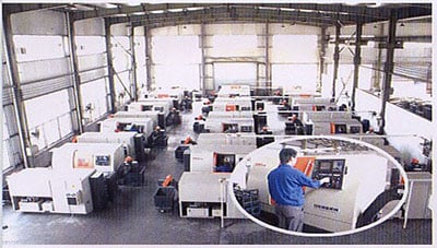
two. Reducing-Edge Computer-Controlled CNC Equipment
3. Bespoke Remedies from Highly Experienced Professionals
four. Customization and OEM Obtainable for Distinct Software
five. Comprehensive Inventory of Spare Elements and Add-ons
six. Well-Developed CZPT Advertising Network
seven. Productive Soon after-Sale Provider Method
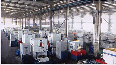
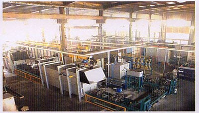
The 219 sets of advanced automatic production equipment supply guarantees for high merchandise top quality. The 167 engineers and professionals with senior specialist titles can layout and build goods to meet up with the specific requires of customers, and OEM customizations are also obtainable with us. Our seem worldwide service network can provide consumers with timely after-income technological solutions.
We are not just a maker and supplier, but also an industry advisor. We function pro-actively with you to supply specialist advice and merchandise recommendations in order to end up with a most cost powerful solution accessible for your distinct software. The consumers we serve CZPT range from end users to distributors and OEMs. Our OEM replacements can be substituted anywhere necessary and ideal for both mend and new assemblies.
| Standard Or Nonstandard: | Standard |
|---|---|
| Application: | Motor, Electric Cars, Motorcycle, Machinery, Marine, Toy, Agricultural Machinery, Car, Mining Machinery, Sugar Machinery |
| Hardness: | Hardened Tooth Surface |
| Manufacturing Method: | Cut Gear |
| Toothed Portion Shape: | Spur Gear |
| Material: | Alloy |
| Samples: |
US$ 0/Piece
1 Piece(Min.Order) | |
|---|
| Customization: |
Available
| Customized Request |
|---|
How to Compare Different Types of Spur Gears
When comparing different types of spur gears, there are several important considerations to take into account. The main considerations include the following: Common applications, Pitch diameter, and Addendum circle. Here we will look at each of these factors in more detail. This article will help you understand what each type of spur gear can do for you. Whether you’re looking to power an electric motor or a construction machine, the right gear for the job will make the job easier and save you money in the long run.
Common applications
Among its many applications, a spur gear is widely used in airplanes, trains, and bicycles. It is also used in ball mills and crushers. Its high speed-low torque capabilities make it ideal for a variety of applications, including industrial machines. The following are some of the common uses for spur gears. Listed below are some of the most common types. While spur gears are generally quiet, they do have their limitations.
A spur gear transmission can be external or auxiliary. These units are supported by front and rear casings. They transmit drive to the accessory units, which in turn move the machine. The drive speed is typically between 5000 and 6000 rpm or 20,000 rpm for centrifugal breathers. For this reason, spur gears are typically used in large machinery. To learn more about spur gears, watch the following video.
The pitch diameter and diametral pitch of spur gears are important parameters. A diametral pitch, or ratio of teeth to pitch diameter, is important in determining the center distance between two spur gears. The center distance between two spur gears is calculated by adding the radius of each pitch circle. The addendum, or tooth profile, is the height by which a tooth projects above the pitch circle. Besides pitch, the center distance between two spur gears is measured in terms of the distance between their centers.
Another important feature of a spur gear is its low speed capability. It can produce great power even at low speeds. However, if noise control is not a priority, a helical gear is preferable. Helical gears, on the other hand, have teeth arranged in the opposite direction of the axis, making them quieter. However, when considering the noise level, a helical gear will work better in low-speed situations.
Construction
The construction of spur gear begins with the cutting of the gear blank. The gear blank is made of a pie-shaped billet and can vary in size, shape, and weight. The cutting process requires the use of dies to create the correct gear geometry. The gear blank is then fed slowly into the screw machine until it has the desired shape and size. A steel gear blank, called a spur gear billet, is used in the manufacturing process.
A spur gear consists of two parts: a centre bore and a pilot hole. The addendum is the circle that runs along the outermost points of a spur gear’s teeth. The root diameter is the diameter at the base of the tooth space. The plane tangent to the pitch surface is called the pressure angle. The total diameter of a spur gear is equal to the addendum plus the dedendum.
The pitch circle is a circle formed by a series of teeth and a diametrical division of each tooth. The pitch circle defines the distance between two meshed gears. The center distance is the distance between the gears. The pitch circle diameter is a crucial factor in determining center distances between two mating spur gears. The center distance is calculated by adding the radius of each gear’s pitch circle. The dedendum is the height of a tooth above the pitch circle.
Other considerations in the design process include the material used for construction, surface treatments, and number of teeth. In some cases, a standard off-the-shelf gear is the most appropriate choice. It will meet your application needs and be a cheaper alternative. The gear will not last for long if it is not lubricated properly. There are a number of different ways to lubricate a spur gear, including hydrodynamic journal bearings and self-contained gears.
Addendum circle
The pitch diameter and addendum circle are two important dimensions of a spur gear. These diameters are the overall diameter of the gear and the pitch circle is the circle centered around the root of the gear’s tooth spaces. The addendum factor is a function of the pitch circle and the addendum value, which is the radial distance between the top of the gear tooth and the pitch circle of the mating gear.
The pitch surface is the right-hand side of the pitch circle, while the root circle defines the space between the two gear tooth sides. The dedendum is the distance between the top of the gear tooth and the pitch circle, and the pitch diameter and addendum circle are the two radial distances between these two circles. The difference between the pitch surface and the addendum circle is known as the clearance.
The number of teeth in the spur gear must not be less than 16 when the pressure angle is twenty degrees. However, a gear with 16 teeth can still be used if its strength and contact ratio are within design limits. In addition, undercutting can be prevented by profile shifting and addendum modification. However, it is also possible to reduce the addendum length through the use of a positive correction. However, it is important to note that undercutting can happen in spur gears with a negative addendum circle.
Another important aspect of a spur gear is its meshing. Because of this, a standard spur gear will have a meshing reference circle called a Pitch Circle. The center distance, on the other hand, is the distance between the center shafts of the two gears. It is important to understand the basic terminology involved with the gear system before beginning a calculation. Despite this, it is essential to remember that it is possible to make a spur gear mesh using the same reference circle.
Pitch diameter
To determine the pitch diameter of a spur gear, the type of drive, the type of driver, and the type of driven machine should be specified. The proposed diametral pitch value is also defined. The smaller the pitch diameter, the less contact stress on the pinion and the longer the service life. Spur gears are made using simpler processes than other types of gears. The pitch diameter of a spur gear is important because it determines its pressure angle, the working depth, and the whole depth.
The ratio of the pitch diameter and the number of teeth is called the DIAMETRAL PITCH. The teeth are measured in the axial plane. The FILLET RADIUS is the curve that forms at the base of the gear tooth. The FULL DEPTH TEETH are the ones with the working depth equal to 2.000 divided by the normal diametral pitch. The hub diameter is the outside diameter of the hub. The hub projection is the distance the hub extends beyond the gear face.
A metric spur gear is typically specified with a Diametral Pitch. This is the number of teeth per inch of the pitch circle diameter. It is generally measured in inverse inches. The normal plane intersects the tooth surface at the point where the pitch is specified. In a helical gear, this line is perpendicular to the pitch cylinder. In addition, the pitch cylinder is normally normal to the helix on the outside.
The pitch diameter of a spur gear is typically specified in millimeters or inches. A keyway is a machined groove on the shaft that fits the key into the shaft’s keyway. In the normal plane, the pitch is specified in inches. Involute pitch, or diametral pitch, is the ratio of teeth per inch of diameter. While this may seem complicated, it’s an important measurement to understand the pitch of a spur gear.
Material
The main advantage of a spur gear is its ability to reduce the bending stress at the tooth no matter the load. A typical spur gear has a face width of 20 mm and will fail when subjected to 3000 N. This is far more than the yield strength of the material. Here is a look at the material properties of a spur gear. Its strength depends on its material properties. To find out what spur gear material best suits your machine, follow the following steps.
The most common material used for spur gears is steel. There are different kinds of steel, including ductile iron and stainless steel. S45C steel is the most common steel and has a 0.45% carbon content. This type of steel is easily obtainable and is used for the production of helical, spur, and worm gears. Its corrosion resistance makes it a popular material for spur gears. Here are some advantages and disadvantages of steel.
A spur gear is made of metal, plastic, or a combination of these materials. The main advantage of metal spur gears is their strength to weight ratio. It is about one third lighter than steel and resists corrosion. While aluminum is more expensive than steel and stainless steel, it is also easier to machine. Its design makes it easy to customize for the application. Its versatility allows it to be used in virtually every application. So, if you have a specific need, you can easily find a spur gear that fits your needs.
The design of a spur gear greatly influences its performance. Therefore, it is vital to choose the right material and measure the exact dimensions. Apart from being important for performance, dimensional measurements are also important for quality and reliability. Hence, it is essential for professionals in the industry to be familiar with the terms used to describe the materials and parts of a gear. In addition to these, it is essential to have a good understanding of the material and the dimensional measurements of a gear to ensure that production and purchase orders are accurate.
editor by CX 2023-04-13
China Driving Gear of Wheeled Tractor Gear-Box Spur Gear Agricultural Machinery worm gearbox
Item Description
Why choose us?
1. HangZhou Xihu (West Lake) Dis.hua Chain Team Co., Ltd. Recognized in 1991, we have 5 subsidiaries in china and have 6 subsidiaries abroad HangZhou Xihu (West Lake) Dis.hua Gear Co., Ltd is 1 of the subsidiaries of it.
2. We specialised in making all sorts of standard chains and particular chains, cylinder gear, common & non-common sprocket and gearbox for center & light variety vehicle and tractor.
3. We have received ISO9001, ISO14001, ISO16969, AAA and API certificates.
four. Our companions amongst globe prime enterprises, this sort of as JOHNDEERE, NEW HOLLAND, HONDA, KUBOTA, YANMAR, and so on.
Method parameter
Module: 1.5 to 3.five
Enamel Quantity: 12 to twenty
Stress Angle: 17° To 25°
O. D: 21 to seventy seven
L(max): 250
Enterprice Introduction
HangZhou Xihu (West Lake) Dis.hua Gear Co., Ltd. A wholly owned subsidiary of HangZhou Xihu (West Lake) Dis.hua Chain Team Co., Ltd. Is the expert maker of cylinder gear, regular & non normal sprocket and gearbox for center & light kind automobile and tractor.
The business possesses far more than 500 sets of superior equipments for hobbing, shaping, shaving, grinding and tests, and imported UNIC carburizing routinely lines for warmth remedy. Our annual outputs of gears, shafts and sprockets are 4 million parts and gearboxes are 50, 000 sets. The primary merchandise are motor gear, gearbox gear, tractor gear and electrical power transmission sprocket, which broadly utilised in center & light kind trucks, agricultural vehicle, tractors and engineering machinery and many others.
Our goods “Feiyu Gears” obtain “The Well-known Brand of ZheJiang Province” and in 2004 we ended up awarded the “Point out level Device of Valuing Contracts and Maintaining on Credit score” by State Administration of Business and Commerce.
High high quality, very best services, reasonable price, we are inclined to cooperate with all the customers and create with each other.
| To Be Negotiated | 50 Sets (Min. Order) |
###
| Application: | Agricultural Machinery |
|---|---|
| Hardness: | Hardened Tooth Surface |
| Manufacturing Method: | Cast Gear |
| Toothed Portion Shape: | Spur Gear |
| Type: | Circular Gear |
| Module: | 1.5 to 3.5 |
###
| Customization: |
|---|
| To Be Negotiated | 50 Sets (Min. Order) |
###
| Application: | Agricultural Machinery |
|---|---|
| Hardness: | Hardened Tooth Surface |
| Manufacturing Method: | Cast Gear |
| Toothed Portion Shape: | Spur Gear |
| Type: | Circular Gear |
| Module: | 1.5 to 3.5 |
###
| Customization: |
|---|
How to Compare Different Types of Spur Gears
When comparing different types of spur gears, there are several important considerations to take into account. The main considerations include the following: Common applications, Pitch diameter, and Addendum circle. Here we will look at each of these factors in more detail. This article will help you understand what each type of spur gear can do for you. Whether you’re looking to power an electric motor or a construction machine, the right gear for the job will make the job easier and save you money in the long run.
Common applications
Among its many applications, a spur gear is widely used in airplanes, trains, and bicycles. It is also used in ball mills and crushers. Its high speed-low torque capabilities make it ideal for a variety of applications, including industrial machines. The following are some of the common uses for spur gears. Listed below are some of the most common types. While spur gears are generally quiet, they do have their limitations.
A spur gear transmission can be external or auxiliary. These units are supported by front and rear casings. They transmit drive to the accessory units, which in turn move the machine. The drive speed is typically between 5000 and 6000 rpm or 20,000 rpm for centrifugal breathers. For this reason, spur gears are typically used in large machinery. To learn more about spur gears, watch the following video.
The pitch diameter and diametral pitch of spur gears are important parameters. A diametral pitch, or ratio of teeth to pitch diameter, is important in determining the center distance between two spur gears. The center distance between two spur gears is calculated by adding the radius of each pitch circle. The addendum, or tooth profile, is the height by which a tooth projects above the pitch circle. Besides pitch, the center distance between two spur gears is measured in terms of the distance between their centers.
Another important feature of a spur gear is its low speed capability. It can produce great power even at low speeds. However, if noise control is not a priority, a helical gear is preferable. Helical gears, on the other hand, have teeth arranged in the opposite direction of the axis, making them quieter. However, when considering the noise level, a helical gear will work better in low-speed situations.
Construction
The construction of spur gear begins with the cutting of the gear blank. The gear blank is made of a pie-shaped billet and can vary in size, shape, and weight. The cutting process requires the use of dies to create the correct gear geometry. The gear blank is then fed slowly into the screw machine until it has the desired shape and size. A steel gear blank, called a spur gear billet, is used in the manufacturing process.
A spur gear consists of two parts: a centre bore and a pilot hole. The addendum is the circle that runs along the outermost points of a spur gear’s teeth. The root diameter is the diameter at the base of the tooth space. The plane tangent to the pitch surface is called the pressure angle. The total diameter of a spur gear is equal to the addendum plus the dedendum.
The pitch circle is a circle formed by a series of teeth and a diametrical division of each tooth. The pitch circle defines the distance between two meshed gears. The center distance is the distance between the gears. The pitch circle diameter is a crucial factor in determining center distances between two mating spur gears. The center distance is calculated by adding the radius of each gear’s pitch circle. The dedendum is the height of a tooth above the pitch circle.
Other considerations in the design process include the material used for construction, surface treatments, and number of teeth. In some cases, a standard off-the-shelf gear is the most appropriate choice. It will meet your application needs and be a cheaper alternative. The gear will not last for long if it is not lubricated properly. There are a number of different ways to lubricate a spur gear, including hydrodynamic journal bearings and self-contained gears.
Addendum circle
The pitch diameter and addendum circle are two important dimensions of a spur gear. These diameters are the overall diameter of the gear and the pitch circle is the circle centered around the root of the gear’s tooth spaces. The addendum factor is a function of the pitch circle and the addendum value, which is the radial distance between the top of the gear tooth and the pitch circle of the mating gear.
The pitch surface is the right-hand side of the pitch circle, while the root circle defines the space between the two gear tooth sides. The dedendum is the distance between the top of the gear tooth and the pitch circle, and the pitch diameter and addendum circle are the two radial distances between these two circles. The difference between the pitch surface and the addendum circle is known as the clearance.
The number of teeth in the spur gear must not be less than 16 when the pressure angle is twenty degrees. However, a gear with 16 teeth can still be used if its strength and contact ratio are within design limits. In addition, undercutting can be prevented by profile shifting and addendum modification. However, it is also possible to reduce the addendum length through the use of a positive correction. However, it is important to note that undercutting can happen in spur gears with a negative addendum circle.
Another important aspect of a spur gear is its meshing. Because of this, a standard spur gear will have a meshing reference circle called a Pitch Circle. The center distance, on the other hand, is the distance between the center shafts of the two gears. It is important to understand the basic terminology involved with the gear system before beginning a calculation. Despite this, it is essential to remember that it is possible to make a spur gear mesh using the same reference circle.
Pitch diameter
To determine the pitch diameter of a spur gear, the type of drive, the type of driver, and the type of driven machine should be specified. The proposed diametral pitch value is also defined. The smaller the pitch diameter, the less contact stress on the pinion and the longer the service life. Spur gears are made using simpler processes than other types of gears. The pitch diameter of a spur gear is important because it determines its pressure angle, the working depth, and the whole depth.
The ratio of the pitch diameter and the number of teeth is called the DIAMETRAL PITCH. The teeth are measured in the axial plane. The FILLET RADIUS is the curve that forms at the base of the gear tooth. The FULL DEPTH TEETH are the ones with the working depth equal to 2.000 divided by the normal diametral pitch. The hub diameter is the outside diameter of the hub. The hub projection is the distance the hub extends beyond the gear face.
A metric spur gear is typically specified with a Diametral Pitch. This is the number of teeth per inch of the pitch circle diameter. It is generally measured in inverse inches. The normal plane intersects the tooth surface at the point where the pitch is specified. In a helical gear, this line is perpendicular to the pitch cylinder. In addition, the pitch cylinder is normally normal to the helix on the outside.
The pitch diameter of a spur gear is typically specified in millimeters or inches. A keyway is a machined groove on the shaft that fits the key into the shaft’s keyway. In the normal plane, the pitch is specified in inches. Involute pitch, or diametral pitch, is the ratio of teeth per inch of diameter. While this may seem complicated, it’s an important measurement to understand the pitch of a spur gear.
Material
The main advantage of a spur gear is its ability to reduce the bending stress at the tooth no matter the load. A typical spur gear has a face width of 20 mm and will fail when subjected to 3000 N. This is far more than the yield strength of the material. Here is a look at the material properties of a spur gear. Its strength depends on its material properties. To find out what spur gear material best suits your machine, follow the following steps.
The most common material used for spur gears is steel. There are different kinds of steel, including ductile iron and stainless steel. S45C steel is the most common steel and has a 0.45% carbon content. This type of steel is easily obtainable and is used for the production of helical, spur, and worm gears. Its corrosion resistance makes it a popular material for spur gears. Here are some advantages and disadvantages of steel.
A spur gear is made of metal, plastic, or a combination of these materials. The main advantage of metal spur gears is their strength to weight ratio. It is about one third lighter than steel and resists corrosion. While aluminum is more expensive than steel and stainless steel, it is also easier to machine. Its design makes it easy to customize for the application. Its versatility allows it to be used in virtually every application. So, if you have a specific need, you can easily find a spur gear that fits your needs.
The design of a spur gear greatly influences its performance. Therefore, it is vital to choose the right material and measure the exact dimensions. Apart from being important for performance, dimensional measurements are also important for quality and reliability. Hence, it is essential for professionals in the industry to be familiar with the terms used to describe the materials and parts of a gear. In addition to these, it is essential to have a good understanding of the material and the dimensional measurements of a gear to ensure that production and purchase orders are accurate.
editor by CX 2023-03-30
China Good Performance Cast Alloy Steel Bevel Gear for Agricultural Machinery gear box
Condition: New
Warranty: 1.5 years
Shape: BEVEL
Applicable Industries: Resorts, Garment Outlets, Developing Substance Shops, Production Plant, Machinery Restore Shops, Meals & Beverage Manufacturing facility, Farms, Restaurant, Property Use, Retail, Food Store, Printing Stores, Construction works , Energy & Mining, Meals & Beverage Shops, Advertising and marketing Company
Bodyweight (KG): five
Showroom Spot: None
Video clip outgoing-inspection: Presented
Machinery Examination Report: Supplied
Marketing Variety: Ordinary Merchandise
Guarantee of main factors: 1 Yr
Core Elements: Equipment
Tooth Profile: HELICAL Equipment
Route: Appropriate Hand
Material: Metal
Processing: Forging
Pressure Angle: 20°
Standard or Nonstandard: Standard
Outer Diameter: Other
Item identify: Bevel Gear
Software: Automobiles
Key phrases: Truck Spiral Bevel Equipment
Service: OEMODM
Right after Guarantee Provider: On the web help
Neighborhood Services Spot: None
Packaging Details: Common Sea Worthy Package deal
Port: ZheJiang , HangZhou
Very good Overall performance Forged Alloy Steel Bevel Gear for Agricultural MachineryOur gear can be common as for every European or American common or unique as for each your drawing or sample. Functions:1.Materials: carbon steel these kinds of as C45, 20CrMnTi, 40Cr, 42CrMo or stainless metal or copper or nylon and so on2.Warmth Therapy: Hardening and Tempering, Higher Frequency Quenching, Carburizing Quenching and so on.3.Standard: European or American standard4.Product: M0.5,M1 .M1,5,M1,7,M2,M2.5,M3, Automobile Parts OEM 33030-0K350 for Hilux Handbook Transmission Gearbox Assembly M4,M5,M6 and so on5.Export Region: Europe and America6.OEM services: make primarily based on your specific sample or drawing and satisfy your need for substantial precision on teeth of gear Good quality with realistic price tag, timely delivery and excellent buyer support. We can also source spur equipment,unique gears, worm equipment,worm wheel,gear spiral bevel gears, massive spur gears,gears wheel,straight bevel gears, helical bevel gears,spur gears,planetary gears, passive gears, milled spur gears, equipment for valve, truck gear, transmission spur equipment,spur bearing equipment, equipment pinions,galvanized gear ect accessible. Normal or unique gears produced by CNC device We create equipment as for every your special samples or drawing and we also make as per common this sort of as Metric common, British requirements, AGMA expectations by CNC equipment Content can be C45, 40Cr, 20CrMnTi, 42CrMo, copper, stainless metal and so on as per your requests There is substantial precision offered as your unique ask for Our equipment is exported to Europe and America in massive quantity and so we are positive that we can help you earn fantastic success! JK First Car Transmission Parts OE 31256845 for CZPT S60 S80 V60 V70 Transmission Gearbox Include Variety A
| M | Z | De | Dp | H | F | d | D | V | Lm | ||||||||||||||||||||||||||||||||||||||||||||||||||||||||||||||||||||||||||
| one.5 | 16twentytwenty fivethirty | 26.132.139.six47.one | 24.thirty.37.five45. | 18.ninetwenty23twenty five | 6tenten12 | 20.3222830 | 8tententwelve | 7.107.40eleven.09thirteen.35 | 128.five1212 | ||||||||||||||||||||||||||||||||||||||||||||||||||||||||||||||||||||||||||
| two | 16twenty25thirty | 34.eightforty two.eightfifty two.8sixty two.8 | 32.forty.50.60. | 23.5252830 | 8twelvefourteen16 | 25.332fortyfifty | 1010twelvetwelve | 9.fifty10.seventy eight14.2817.78 | 141212.312.eight | ||||||||||||||||||||||||||||||||||||||||||||||||||||||||||||||||||||||||||
| .2.five | 16202530 | 43.553.666.seventy eight.five | 40.50.sixty two.fiveseventy five. | 28.one30.533.five35.5 | 10twelve15eighteen | 30.34050fifty five | 1212fifteenfifteen | 11.9015.4319.4823.63 | 15sixteensixteen16 | ||||||||||||||||||||||||||||||||||||||||||||||||||||||||||||||||||||||||||
| three | 16twenty25thirty | 52.twosixty four.two79.2ninety four.2 | 48.sixty.seventy five.ninety. | 31.7353840 | 12eighteen2022 | 40.threeforty five5560 | 1515fifteen20 | 14.30sixteen. ll verify.
How to Design a Forging Spur GearBefore you start designing your own spur gear, you need to understand its main components. Among them are Forging, Keyway, Spline, Set screw and other types. Understanding the differences between these types of spur gears is essential for making an informed decision. To learn more, keep reading. Also, don’t hesitate to contact me for assistance! Listed below are some helpful tips and tricks to design a spur gear. Hopefully, they will help you design the spur gear of your dreams. Forging spur gearsForging spur gears is one of the most important processes of automotive transmission components. The manufacturing process is complex and involves several steps, such as blank spheroidizing, hot forging, annealing, phosphating, and saponification. The material used for spur gears is typically 20CrMnTi. The process is completed by applying a continuous through extrusion forming method with dies designed for the sizing band length L and Splitting angle thickness T. Set screw spur gearsA modern industry cannot function without set screw spur gears. These gears are highly efficient and are widely used in a variety of applications. Their design involves the calculation of speed and torque, which are both critical factors. The MEP model, for instance, considers the changing rigidity of a tooth pair along its path. The results are used to determine the type of spur gear required. Listed below are some tips for choosing a spur gear: Keyway spur gearsIn today’s modern industry, spur gear transmissions are widely used to transfer power. These types of transmissions provide excellent efficiency but can be susceptible to power losses. These losses must be estimated during the design process. A key component of this analysis is the calculation of the contact area (2b) of the gear pair. However, this value is not necessarily applicable to every spur gear. Here are some examples of how to calculate this area. (See Figure 2) Spline spur gearsWhen considering the types of spur gears that are used, it’s important to note the differences between the two. A spur gear, also called an involute gear, generates torque and regulates speed. It’s most common in car engines, but is also used in everyday appliances. However, one of the most significant drawbacks of spur gears is their noise. Because spur gears mesh only one tooth at a time, they create a high amount of stress and noise, making them unsuitable for everyday use. Stainless steel spur gears are manufactured using different techniques, which depend on the material and the application. The most common process used in manufacturing them is cutting. Other processes involve rolling, casting, and forging. In addition, plastic spur gears are produced by injection molding, depending on the quantity of production required. SUS303 and SUS304 stainless steel spur gears can be made using a variety of materials, including structural carbon steel S45C, gray cast iron FC200, nonferrous metal C3604, engineering plastic MC901, and stainless steel. Stainless steel spur gearsThere are several things to look for in a stainless steel spur gear, including the diametral pitch, the number of teeth per unit diameter, and the angular velocity of the teeth. All of these aspects are critical to the performance of a spur gear, and the proper dimensional measurements are essential to the design and functionality of a spur gear. Those in the industry should be familiar with the terms used to describe spur gear parts, both to ensure clarity in production and in purchase orders.
China Free Forging Forged Gear for Machinery gear cycleSolution Description
Open die forging’s information: Rewards of Open up Die Forging We are China Forging tubeForging tube producer supply best Forging tubeForging
###
###
###
###
Types of Miter GearsThe different types of miter gears include Hypoid, Crown, and Spiral. To learn more, read on. In addition, you’ll learn about their differences and similarities. This article will provide an overview of the different types of miter gears. You can also choose the type that fits your needs by using the guide below. After you’ve read it, you’ll know how to use them in your project. You’ll also learn how to pair them up by hand, which is particularly useful if you’re working on a mechanical component. Bevel gearsBevel and miter gears are both used to connect two shafts that have different axes. In most cases, these gears are used at right angles. The pitch cone of a bevel gear has the same shape as that of a spur gear, except the tooth profile is slightly tapered and has variable depth. The pinions of a bevel gear are normally straight, but can be curved or skew-shaped. They can also have an offset crown wheel with straight teeth relative to the axis. Hypoid bevel gearsWhen it comes to designing hypoid bevel gears for miter and other kinds of gears, there are several important parameters to consider. In order to produce high-quality gearings, the mounting distance between the gear teeth and the pinion must be within a predefined tolerance range. In other words, the mounting distance between the gear teeth and pinion must be 0.05 mm or less. Crown bevel gearsWhen choosing crown bevels for a miter gear, you will need to consider a number of factors. Specifically, you will need to know the ratio of the tooth load to the bevel gear pitch radius. This will help you choose a bevel gear that possesses the right amount of excitation and load capacity. Crown bevels are also known as helical gears, which are a combination of two bevel gear types. Spiral miter gearsSpiral bevel gears are produced by machining the face surface of the teeth. The process follows the Hertz theory of elastic contact, where the dislocations are equivalent to small significant dimensions of the contact area and the relative radii of curvature. This method assumes that the surfaces are parallel and that the strains are small. Moreover, it can reduce noise. This makes spiral bevel gears an ideal choice for high-speed applications.
China manufacturer & factory supplier for Gearbox in Las Vegas United States for Agricultural Machinery TYPE RV-010 With high quality best price & service
Our abilities go far past the scope of our catalog. Dependent on buyer need, we now stock solid collars with oversized bores for programs exactly where the regular tolerance does not let for sufficient clearance. We also supply a variety of finishes for sound and split collar such as yellow zinc, nickel and chrome. A lot of are even stocked for off-the-shelf shipping and delivery. We also manufacture and inventory strong collars with 2 established screws, with through holes, and with out holes. Collars are available in inch and metric sizes. Large sequence clamp-kind collars and threaded collars are also available. We can even offer sq. bore collars for quantity needs. And if your particular demands repeat often, we are happy to stock elements for scheduled releases. Whatsoever your collar needs, Lucas Industrial is your provider for high quality value – efficient parts. We are aiming to satisfy the calls for of the consumers around the globe.. a specialized supplier of a complete variety of chains, sprockets, gears, equipment racks, V-belts, couplings and reducers, pto shaft, agricultural gearboxes….
Overview
Swift Particulars
Packaging & Delivery
On-line Customization
Item Description
Packaging & Shipping
Our Companies Also I would like to consider this chance to give a brief introduction of our At any time-Electrical power business: Our business is a well-known company of agriculture gearbox,worm reduce gearbox, PTO shafts, Sprockets ,rollar chains, bevel equipment, pulleys and racks in china. We have exported several merchandise to our consumers all above the globe, we have long-time expertise and powerful technologies help. Some of our customer : -Ø Our Business with in excess of twelve year’s background and a thousand employees and 20 sales. you also can examine our internet site to know for far more information, if you require our merchandise catalogue, please speak to with us.
Organization Data
Best China manufacturer & factory china in Pointe-Noire Congo manufacturer Agriculture Machinery Parts Cultivator Parts Plow Tip With high quality best price
Our product variety contains all types of helical gear, spur gear, bevel gear, equipment rack, worm gear, sprockets,chains, bearings, pto shaft, agricultural gearboxes.
Overview
Quick Details
Supply Capability
Packaging & Shipping and delivery
On-line Customization
Associated Goods Large Good quality Warmth Treatment method 60si2mn Lawn Mower Blade Merchandise Description
Packaging & Shipping
MOQ: 3 Tons White PE Sheet Port: Tianjin, Xingang Payment: LC, T/T, Western Union, T/T thirty% deposit before manufacturing and the equilibrium paid out ahead of shipping Shipping Time: Within 2 weeks Packaging: Masked film and packed by picket pallet
Our Solutions
1. We support ODM & OEM.
Organization Data
ZheJiang China . EPG – a single of the biggest Agri-Machinery parts manufacturing facility in China EPG China Machinery Co. Ltd. formerly acknowledged as jianhuxian EPG China rotary knife manufacturing unit, specializing in the manufacturing of agricultural items. Foremost goods are rotary knives, knives reclamation, pastoral administration knives, wooden reducing blade, scarifier plough, shovel, S-formed springs, disc plough, cultivator auxiliary areas and other machinery goods.
Display
1. Can in accordance to client design and style and production of items? two. You can offer some samples for me? three. I am a modest wholesaler, do you take little get?
| |||||||||||||||||||||||||||||||||||||||||||||||||||||||||||||||||||||||||||