Condition: New
Warranty: Unavailable
Shape: Spur
Applicable Industries: Building Material Shops, Manufacturing Plant, Machinery Repair Shops, Food & Beverage Factory, Home Use, Printing Shops, Construction works , Energy & Mining, Food & Beverage Shops, Advertising Company
Weight (KG): 0.1
Showroom Location: None
Video outgoing-inspection: Provided
Machinery Test Report: Provided
Marketing Type: Ordinary Product
Warranty of core components: More than 5 years
Core Components: Gearbox, Gear
Material: ABS
Processing: Grinding
Application: Transmission Gearbox
Quality: good
After Warranty Service: Video technical support
Packaging Details: netural packing
| Product Features | ||
| *Brand | ADX | |
| *Product name | Plastic Gearbox | |
| *Color | Customize | |
| *Material | POM, PEEK, ABS, Nylon, PVC, etc | |
| *Lead Time | 1-2 weeks for samples, 3-4 weeks for mass production | |
| *Quality Assurance | ISO9001:2015 | |
| *Drawing Accepted | Solid Works, Z2 type Locking element instead of KTR,Tollok(TLK),SATI,Ringfeder Pro/Engineer, Auto CAD(DXF, DWG), PDF | |
| *Processing | CNC turning, CNC milling, CNC turn-milled, Laser cutting | |

Types of Miter Gears
The different types of miter gears include Hypoid, Crown, and Spiral. To learn more, read on. In addition, you’ll learn about their differences and similarities. This article will provide an overview of the different types of miter gears. You can also choose the type that fits your needs by using the guide below. After you’ve read it, you’ll know how to use them in your project. You’ll also learn how to pair them up by hand, which is particularly useful if you’re working on a mechanical component.
Bevel gears
Bevel and miter gears are both used to connect two shafts that have different axes. In most cases, these gears are used at right angles. The pitch cone of a bevel gear has the same shape as that of a spur gear, except the tooth profile is slightly tapered and has variable depth. The pinions of a bevel gear are normally straight, but can be curved or skew-shaped. They can also have an offset crown wheel with straight teeth relative to the axis.
In addition to their industrial applications, miter gears are found in agriculture, bottling, printing, and various industrial sectors. They are used in coal mining, oil exploration, and chemical processes. They are an important part of conveyors, elevators, kilns, and more. In fact, miter gears are often used in machine tools, like forklifts and jigsaws.
When considering which gear is right for a certain application, you’ll need to think about the application and the design goals. For example, you’ll want to know the maximum load that the gear can carry. You can use computer simulation programs to determine the exact torque required for a specific application. Miter gears are bevel gears that are geared on a single axis, not two.
To calculate the torque required for a particular application, you’ll need to know the MA of each bevel gear. Fortunately, you can now do so with CZPT. With the help of this software, you can generate 3D models of spiral bevel gears. Once you’ve created your model, you can then machine it. This can make your job much easier! And it’s fun!
In terms of manufacturing, straight bevel gears are the easiest to produce. The earliest method for this type of gear is a planer with an indexing head. Since the development of CNC machining, however, more effective manufacturing methods have been developed. These include CZPT, Revacycle, and Coniflex systems. The CZPT uses the Revacycle system. You can also use a CNC mill to manufacture spiral bevel gears.
Hypoid bevel gears
When it comes to designing hypoid bevel gears for miter and other kinds of gears, there are several important parameters to consider. In order to produce high-quality gearings, the mounting distance between the gear teeth and the pinion must be within a predefined tolerance range. In other words, the mounting distance between the gear teeth and pinion must be 0.05 mm or less.
To make this possible, the hypoid bevel gearset mesh is designed to involve sliding action. The result is a quiet transmission. It also means that higher speeds are possible without increasing noise levels. In comparison, bevel gears tend to be noisy at high speeds. For these reasons, the hypoid gearset is the most efficient way to build miter gears. However, it’s important to keep in mind that hypoid gears are not for every application.
Hypoid bevel gears are analogous to spiral bevels, but they don’t have intersecting axes. Because of this, they can produce larger pinions with smooth engagement. Crown bevel gears, on the other hand, have a 90-degree pitch and parallel teeth. Their geometry and pitch is unique, and they have particular geometrical properties. There are different ways to express pitch. The diametral pitch is the number of teeth, while circumferential measurement is called the circumference.
The face-milling method is another technique used for the manufacture of hypoid and spiral bevel gears. Face-milling allows gears to be ground for high accuracy and surface finish. It also allows for the elimination of heat treatment and facilitates the creation of predesigned ease-off topographies. Face-milling increases mechanical resistance by as much as 20%. It also reduces noise levels.
The ANSI/AGMA/ISO standards for geometric dimensioning differ from the best practices for manufacturing hypoid and bevel gears. The violation of common datum surfaces leads to a number of geometrical dimensioning issues. Moreover, hypoid gears need to be designed to incorporate the base pitches of the mating pinion and the hypoid bevel gear. This is not possible without knowing the base pitch of the gear and the mating pinion.
Crown bevel gears
When choosing crown bevels for a miter gear, you will need to consider a number of factors. Specifically, you will need to know the ratio of the tooth load to the bevel gear pitch radius. This will help you choose a bevel gear that possesses the right amount of excitation and load capacity. Crown bevels are also known as helical gears, which are a combination of two bevel gear types.
These bevel gears differ from spiral bevels because the bevels are not intersected. This gives you the flexibility of using a larger pinion and smoother engagement. Crown bevel gears are also named for their different tooth portions: the toe, or the part of the gear closest to the bore, and the heel, or the outermost diameter. The tooth height is smaller at the toe than it is at the heel, but the height of the gear is the same at both places.
Crown bevel gears are cylindrical, with teeth that are angled at an angle. They have a 1:1 gear ratio and are used for miter gears and spur gears. Crown bevel gears have a tooth profile that is the same as spur gears but is slightly narrower at the tip, giving them superior quietness. Crown bevel gears for miter gears can be made with an offset pinion.
There are many other options available when choosing a Crown bevel gear for miter gears. The material used for the gears can vary from plastics to pre-hardened alloys. If you are concerned with the material’s strength, you can choose a pre-hardened alloy with a 32-35 Rc hardness. This alloy also has the advantage of being more durable than plastic. In addition to being stronger, crown bevel gears are also easier to lubricate.
Crown bevel gears for miter gears are similar to spiral bevels. However, they have a hyperbolic, not conical, pitch surface. The pinion is often offset above or below the center of the gear, which allows for a larger diameter. Crown bevel gears for miter gears are typically larger than hypoid gears. The hypoid gear is commonly used in automobile rear axles. They are useful when the angle of rotation is 90 degrees. And they can be used for 1:1 ratios.
Spiral miter gears
Spiral bevel gears are produced by machining the face surface of the teeth. The process follows the Hertz theory of elastic contact, where the dislocations are equivalent to small significant dimensions of the contact area and the relative radii of curvature. This method assumes that the surfaces are parallel and that the strains are small. Moreover, it can reduce noise. This makes spiral bevel gears an ideal choice for high-speed applications.
The precision machining of CZPT spiral miter gears reduces backlash. They feature adjustable locking nuts that can precisely adjust the spacing between the gear teeth. The result is reduced backlash and maximum drive life. In addition, these gears are flexible enough to accommodate design changes late in the production process, reducing risk for OEMs and increasing efficiency and productivity. The advantages of spiral miter gears are outlined below.
Spiral bevel gears also have many advantages. The most obvious of these advantages is that they have large-diameter shafts. The larger shaft size allows for a larger diameter gear, but this means a larger gear housing. In turn, this reduces ground clearance, interior space, and weight. It also makes the drive axle gear larger, which reduces ground clearance and interior space. Spiral bevel gears are more efficient than spiral bevel gears, but it may be harder to find the right size for your application.
Another benefit of spiral miter gears is their small size. For the same amount of power, a spiral miter gear is smaller than a straight cut miter gear. Moreover, spiral bevel gears are less likely to bend or pit. They also have higher precision properties. They are suitable for secondary operations. Spiral miter gears are more durable than straight cut ones and can operate at higher speeds.
A key feature of spiral miter gears is their ability to resist wear and tear. Because they are constantly being deformed, they tend to crack in a way that increases their wear and tear. The result is a harder gear with a more contoured grain flow. But it is possible to restore the quality of your gear through proper maintenance. If you have a machine, it would be in your best interest to replace worn parts if they aren’t functioning as they should.


editor by Cx 2023-07-13
China 1400rpm Rv Series Reduction Gearbox 1 50 Ratio Gear Nmrv Series Worm Reducer hypoid bevel gear
Error:获取返回内容失败,
Your session has expired. Please reauthenticate.

Types of Bevel Gears
Bevel Gears are used in a number of industries. They are used in wheeled excavators, dredges, conveyor belts, mill actuators, and rail transmissions. A bevel gear’s spiral or angled bevel can make it suitable for confined spaces. It is also used in robotics and vertical supports of rolling mills. You can use bevel gears in food processing processes. For more information on bevel gears, read on.
Spiral bevel gear
Spiral bevel gears are used to transmit power between two shafts in a 90-degree orientation. They have curved or oblique teeth and can be fabricated from various metals. Bestagear is one manufacturer specializing in medium to large spiral bevel gears. They are used in the mining, metallurgical, marine, and oil fields. Spiral bevel gears are usually made from steel, aluminum, or phenolic materials.
Spiral bevel gears have many advantages. Their mesh teeth create a less abrupt force transfer. They are incredibly durable and are designed to last a long time. They are also less expensive than other right-angle gears. They also tend to last longer, because they are manufactured in pairs. The spiral bevel gear also reduces noise and vibration from its counterparts. Therefore, if you are in need of a new gear set, spiral bevel gears are the right choice.
The contact between spiral bevel gear teeth occurs along the surface of the gear tooth. The contact follows the Hertz theory of elastic contact. This principle holds for small significant dimensions of the contact area and small relative radii of curvature of the surfaces. In this case, strains and friction are negligible. A spiral bevel gear is a common example of an inverted helical gear. This gear is commonly used in mining equipment.
Spiral bevel gears also have a backlash-absorbing feature. This feature helps secure the thickness of the oil film on the gear surface. The shaft axis, mounting distance, and angle errors all affect the tooth contact on a spiral bevel gear. Adjusting backlash helps to correct these problems. The tolerances shown above are common for bevel gears. In some cases, manufacturers make slight design changes late in the production process, which minimizes the risk to OEMs.
Straight bevel gear
Straight bevel gears are among the easiest types of gears to manufacture. The earliest method used to manufacture straight bevel gears was to use a planer equipped with an indexing head. However, improvements have been made in manufacturing methods after the introduction of the Revacycle system and the Coniflex. The latest technology allows for even more precise manufacturing. Both of these manufacturing methods are used by CZPT. Here are some examples of straight bevel gear manufacturing.
A straight bevel gear is manufactured using two kinds of bevel surfaces, namely, the Gleason method and the Klingelnberg method. Among the two, the Gleason method is the most common. Unlike other types of gear, the CZPT method is not a universal standard. The Gleason system has higher quality gears, since its adoption of tooth crowning is the most effective way to make gears that tolerate even small assembly errors. It also eliminates the stress concentration in the bevelled edges of the teeth.
The gear’s composition depends on the application. When durability is required, a gear is made of cast iron. The pinion is usually three times harder than the gear, which helps balance wear. Other materials, such as carbon steel, are cheaper, but are less resistant to corrosion. Inertia is another critical factor to consider, since heavier gears are more difficult to reverse and stop. Precision requirements may include the gear pitch and diameter, as well as the pressure angle.
Involute geometry of a straight bevel gear is often computed by varying the surface’s normal to the surface. Involute geometry is computed by incorporating the surface coordinates and the theoretical tooth thickness. Using the CMM, the spherical involute surface can be used to determine tooth contact patterns. This method is useful when a roll tester tooling is unavailable, because it can predict the teeth’ contact pattern.
Hypoid bevel gear
Hypoid bevel gears are an efficient and versatile speed reduction solution. Their compact size, high efficiency, low noise and heat generation, and long life make them a popular choice in the power transmission and motion control industries. The following are some of the benefits of hypoid gearing and why you should use it. Listed below are some of the key misperceptions and false assumptions of this gear type. These assumptions may seem counterintuitive at first, but will help you understand what this gear is all about.
The basic concept of hypoid gears is that they use two non-intersecting shafts. The smaller gear shaft is offset from the larger gear shaft, allowing them to mesh without interference and support each other securely. The resulting torque transfer is improved when compared to conventional gear sets. A hypoid bevel gear is used to drive the rear axle of an automobile. It increases the flexibility of machine design and allows the axes to be freely adjusted.
In the first case, the mesh of the two bodies is obtained by fitting the hyperboloidal cutter to the desired gear. Its geometric properties, orientation, and position determine the desired gear. The latter is used if the desired gear is noise-free or is required to reduce vibrations. A hyperboloidal cutter, on the other hand, meshes with two toothed bodies. It is the most efficient option for modeling hypoid gears with noise concerns.
The main difference between hypoid and spiral bevel gears is that the hypoid bevel gear has a larger diameter than its counterparts. They are usually found in 1:1 and 2:1 applications, but some manufacturers also provide higher ratios. A hypoid gearbox can achieve speeds of three thousand rpm. This makes it the preferred choice in a variety of applications. So, if you’re looking for a gearbox with a high efficiency, this is the gear for you.
Addendum and dedendum angles
The addendum and dedendum angles of a bevel gear are used to describe the shape and depth of the teeth of the gear. Each tooth of the gear has a slightly tapered surface that changes in depth. These angles are defined by their addendum and dedendum distances. Addendum angle is the distance between the top land and the bottom surface of the teeth, while dedendum angle is the distance between the pitch surface and the bottom surface of the teeth.
The pitch angle is the angle formed by the apex point of the gear’s pitch cone with the pitch line of the gear shaft. The dedendum angle, on the other hand, is the depth of the tooth space below the pitch line. Both angles are used to measure the shape of a bevel gear. The addendum and dedendum angles are important for gear design.
The dedendum and addendum angles of a bevel gear are determined by the base contact ratio (Mc) of the two gears. The involute curve is not allowed to extend within the base diameter of the bevel gear. The base diameter is also a critical measurement for the design of a gear. It is possible to reduce the involute curve to match the involute curve, but it must be tangential to the involute curve.
The most common application of a bevel gear is the automotive differential. They are used in many types of vehicles, including cars, trucks, and even construction equipment. They are also used in the marine industry and aviation. Aside from these two common uses, there are many other uses for bevel gears. And they are still growing in popularity. But they’re a valuable part of automotive and industrial gearing systems.
Applications of bevel gears
Bevel gears are used in a variety of applications. They are made of various materials depending on their weight, load, and application. For high-load applications, ferrous metals such as grey cast iron are used. These materials have excellent wear resistance and are inexpensive. For lower-weight applications, steel or non-metals such as plastics are used. Some bevel gear materials are considered noiseless. Here are some of their most common uses.
Straight bevel gears are the easiest to manufacture. The earliest method of manufacturing them was with a planer with an indexing head. Modern manufacturing methods introduced the Revacycle and Coniflex systems. For industrial gear manufacturing, the CZPT uses the Revacycle system. However, there are many types of bevel gears. This guide will help you choose the right material for your next project. These materials can withstand high rotational speeds and are very strong.
Bevel gears are most common in automotive and industrial machinery. They connect the driveshaft to the wheels. Some even have a 45-degree bevel. These gears can be placed on a bevel surface and be tested for their transmission capabilities. They are also used in testing applications to ensure proper motion transmission. They can reduce the speed of straight shafts. Bevel gears can be used in many industries, from marine to aviation.
The simplest type of bevel gear is the miter gear, which has a 1:1 ratio. It is used to change the axis of rotation. The shafts of angular miter bevel gears can intersect at any angle, from 45 degrees to 120 degrees. The teeth on the bevel gear can be straight, spiral, or Zerol. And as with the rack and pinion gears, there are different types of bevel gears.
editor by Cx 2023-06-27
China Custom Nylon gear large module planetary gear non-standard precision reduction plastic gear for machine straight bevel gear
Issue: New
Guarantee: Unavailable
Form: Spur
Applicable Industries: Creating Materials Stores, Producing Plant, Machinery Mend Outlets, Foods & Beverage Manufacturing unit, Home Use, Printing Outlets, Development works , Vitality & Mining, Foods & Beverage Outlets, Promoting Company
Bodyweight (KG): .01
Showroom Location: None
Video clip outgoing-inspection: Provided
Equipment Examination Report: Offered
Marketing and advertising Kind: Ordinary Product
Warranty of core elements: A lot more than 5 many years
Main Components: Gearbox, Gear
Materials: POM
Processing: Grinding
Software: Transmission Gearbox
Certification: ISO9001
Good quality: great
Neighborhood Provider Area: None
Packaging Particulars: netural packing
| Product Characteristics | ||
| *Brand name | ADX | |
| *Product name | Plastic Gears | |
| *Colour | Customize | |
| *Material | POM, PEEK, Ab muscles, Nylon, PVC, and so on | |
| *Lead Time | 1-2 months for samples, 3-4 months for mass production | |
| *High quality Assurance | ISO9001:2015 | |
| *Drawing Accepted | Solid Functions, China Wholesale OEM Support Gear Rack Garage Sliding Doorway Components Professional/Engineer, Automobile CAD(DXF, DWG), PDF | |
| *Processing | CNC turning, CNC milling, CNC change-milled, Laser chopping | |
Helical, Straight-Cut, and Spiral-Bevel Gears
If you are planning to use bevel gears in your machine, you need to understand the differences between Helical, Straight-cut, and Spiral bevel gears. This article will introduce you to these gears, as well as their applications. The article will also discuss the benefits and disadvantages of each type of bevel gear. Once you know the differences, you can choose the right gear for your machine. It is easy to learn about spiral bevel gears.
Spiral bevel gear
Spiral bevel gears play a critical role in the aeronautical transmission system. Their failure can cause devastating accidents. Therefore, accurate detection and fault analysis are necessary for maximizing gear system efficiency. This article will discuss the role of computer aided tooth contact analysis in fault detection and meshing pinion position errors. You can use this method to detect problems in spiral bevel gears. Further, you will learn about its application in other transmission systems.
Spiral bevel gears are designed to mesh the gear teeth more slowly and appropriately. Compared to straight bevel gears, spiral bevel gears are less expensive to manufacture with CNC machining. Spiral bevel gears have a wide range of applications and can even be used to reduce the size of drive shafts and bearings. There are many advantages to spiral bevel gears, but most of them are low-cost.
This type of bevel gear has three basic elements: the pinion-gear pair, the load machine, and the output shaft. Each of these is in torsion. Torsional stiffness accounts for the elasticity of the system. Spiral bevel gears are ideal for applications requiring tight backlash monitoring and high-speed operations. CZPT precision machining and adjustable locknuts reduce backlash and allow for precise adjustments. This reduces maintenance and maximizes drive lifespan.
Spiral bevel gears are useful for both high-speed and low-speed applications. High-speed applications require spiral bevel gears for maximum efficiency and speed. They are also ideal for high-speed and high torque, as they can reduce rpm without affecting the vehicle’s speed. They are also great for transferring power between two shafts. Spiral bevel gears are widely used in automotive gears, construction equipment, and a variety of industrial applications.
Hypoid bevel gear
The Hypoid bevel gear is similar to the spiral bevel gear but differs in the shape of the teeth and pinion. The smallest ratio would result in the lowest gear reduction. A Hypoid bevel gear is very durable and efficient. It can be used in confined spaces and weighs less than an equivalent cylindrical gear. It is also a popular choice for high-torque applications. The Hypoid bevel gear is a good choice for applications requiring a high level of speed and torque.
The Hypoid bevel gear has multiple teeth that mesh with each other at the same time. Because of this, the gear transmits torque with very little noise. This allows it to transfer a higher torque with less noise. However, it must be noted that a Hypoid bevel gear is usually more expensive than a spiral bevel gear. The cost of a Hypoid bevel gear is higher, but its benefits make it a popular choice for some applications.
A Hypoid bevel gear can be made of several types. They may differ in the number of teeth and their spiral angles. In general, the smaller hypoid gear has a larger pinion than its counterpart. This means that the hypoid gear is more efficient and stronger than its bevel cousin. It can even be nearly silent if it is well lubricated. Once you’ve made the decision to get a Hypoid bevel gear, be sure to read up on its benefits.
Another common application for a Hypoid bevel gear is in automobiles. These gears are commonly used in the differential in automobiles and trucks. The torque transfer characteristics of the Hypoid gear system make it an excellent choice for many applications. In addition to maximizing efficiency, Hypoid gears also provide smoothness and efficiency. While some people may argue that a spiral bevel gear set is better, this is not an ideal solution for most automobile assemblies.
Helical bevel gear
Compared to helical worm gears, helical bevel gears have a small, compact housing and are structurally optimized. They can be mounted in various ways and feature double chamber shaft seals. In addition, the diameter of the shaft and flange of a helical bevel gear is comparable to that of a worm gear. The gear box of a helical bevel gear unit can be as small as 1.6 inches, or as large as eight cubic feet.
The main characteristic of helical bevel gears is that the teeth on the driver gear are twisted to the left and the helical arc gears have a similar design. In addition to the backlash, the teeth of bevel gears are twisted in a clockwise and counterclockwise direction, depending on the number of helical bevels in the bevel. It is important to note that the tooth contact of a helical bevel gear will be reduced by about ten to twenty percent if there is no offset between the two gears.
In order to create a helical bevel gear, you need to first define the gear and shaft geometry. Once the geometry has been defined, you can proceed to add bosses and perforations. Then, specify the X-Y plane for both the gear and the shaft. Then, the cross section of the gear will be the basis for the solid created after revolution around the X-axis. This way, you can make sure that your gear will be compatible with the pinion.
The development of CNC machines and additive manufacturing processes has greatly simplified the manufacturing process for helical bevel gears. Today, it is possible to design an unlimited number of bevel gear geometry using high-tech machinery. By utilizing the kinematics of a CNC machine center, you can create an unlimited number of gears with the perfect geometry. In the process, you can make both helical bevel gears and spiral bevel gears.
Straight-cut bevel gear
A straight-cut bevel gear is the easiest to manufacture. The first method of manufacturing a straight bevel gear was to use a planer with an indexing head. Later, more efficient methods of manufacturing straight bevel gears were introduced, such as the Revacycle system and the Coniflex system. The latter method is used by CZPT. Here are some of the main benefits of using a straight-cut bevel gear.
A straight-cut bevel gear is defined by its teeth that intersect at the axis of the gear when extended. Straight-cut bevel gears are usually tapered in thickness, with the outer part being larger than the inner portion. Straight-cut bevel gears exhibit instantaneous lines of contact, and are best suited for low-speed, static-load applications. A common application for straight-cut bevel gears is in the differential systems of automobiles.
After being machined, straight-cut bevel gears undergo heat treatment. Case carburizing produces gears with surfaces of 60-63 Rc. Using this method, the pinion is 3 Rc harder than the gear to equalize wear. Flare hardening, flame hardening, and induction hardening methods are rarely used. Finish machining includes turning the outer and inner diameters and special machining processes.
The teeth of a straight-cut bevel gear experience impact and shock loading. Because the teeth of both gears come into contact abruptly, this leads to excessive noise and vibration. The latter limits the speed and power transmission capacity of the gear. On the other hand, a spiral-cut bevel gear experiences gradual but less-destructive loading. It can be used for high-speed applications, but it should be noted that a spiral-cut bevel gear is more complicated to manufacture.
Spur-cut bevel gear
CZPT stocks bevel gears in spiral and straight tooth configurations, in a range of ratios from 1.5 to five. They are also highly remachinable except for the teeth. Spiral bevel gears have a low helix angle and excellent precision properties. CZPT stock bevel gears are manufactured using state-of-the-art technologies and know-how. Compared with spur-cut gears, these have a longer life span.
To determine the strength and durability of a spur-cut bevel gear, you can calculate its MA (mechanical advantage), surface durability (SD), and tooth number (Nb). These values will vary depending on the design and application environment. You can consult the corresponding guides, white papers, and technical specifications to find the best gear for your needs. In addition, CZPT offers a Supplier Discovery Platform that allows you to discover more than 500,000 suppliers.
Another type of spur gear is the double helical gear. It has both left-hand and right-hand helical teeth. This design balances thrust forces and provides extra gear shear area. Helical gears, on the other hand, feature spiral-cut teeth. While both types of gears may generate significant noise and vibration, helical gears are more efficient for high-speed applications. Spur-cut bevel gears may also cause similar effects.
In addition to diametral pitch, the addendum and dedendum have other important properties. The dedendum is the depth of the teeth below the pitch circle. This diameter is the key to determining the center distance between two spur gears. The radius of each pitch circle is equal to the entire depth of the spur gear. Spur gears often use the addendum and dedendum angles to describe the teeth.
editor by czh 2023-02-17
China RV Series Reduction Gear Machine with Right Angle Shaft bevel gearbox
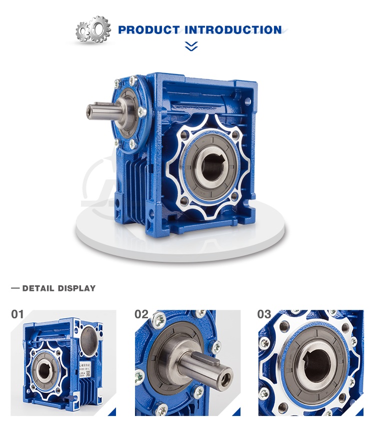
Solution Description
RV Sequence Reduction gear machine With Appropriate Angle Shaft
NMRV 571-150 worm gear box with flange and electrical motor
NMRV+NMRV Double Phase Arrangement Reduction Equipment Box
RV Series Worm Gearbox
worm speed reducer
nmrv worm equipment motor
RV Series
Like RV / NMRV / NRV.
Principal Characteristic of RV Sequence Worm Gearbox
RV series worm equipment reducer is a new-era product produced by CZPT on the basis of perfecting WJ sequence products with a compromise of innovative technological innovation each at residence and abroad.
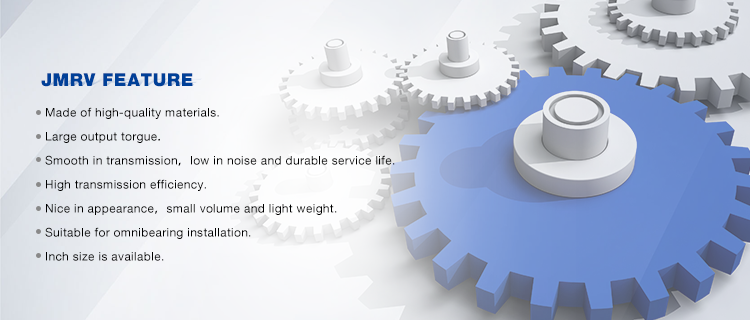
1. Large-quality aluminum alloy, light in fat and non-rusting.
2. Big in output torque.
three. Sleek operating and reduced sound,tough in dreadful problems.
4. High radiation efficiency.
5. Good-seeking visual appeal, sturdy in service lifestyle and tiny volume.
six. Suitable for omnibearing set up.
Principal Components of RV Series Worm Gearbox
1. Housing: die-cast aluminum alloy(frame measurement: 571 to 090), cast iron(frame size: 110 to 150).
2. Worm: 20Crm, carbonization quencher heat remedy helps make the surface hardness of worm gears up to fifty six-sixty two HRX, keep carbonization layer’s thickness in between .3 and .5mm right after exact grinding.
3. Worm Wheel: wearable stannum bronze alloy.
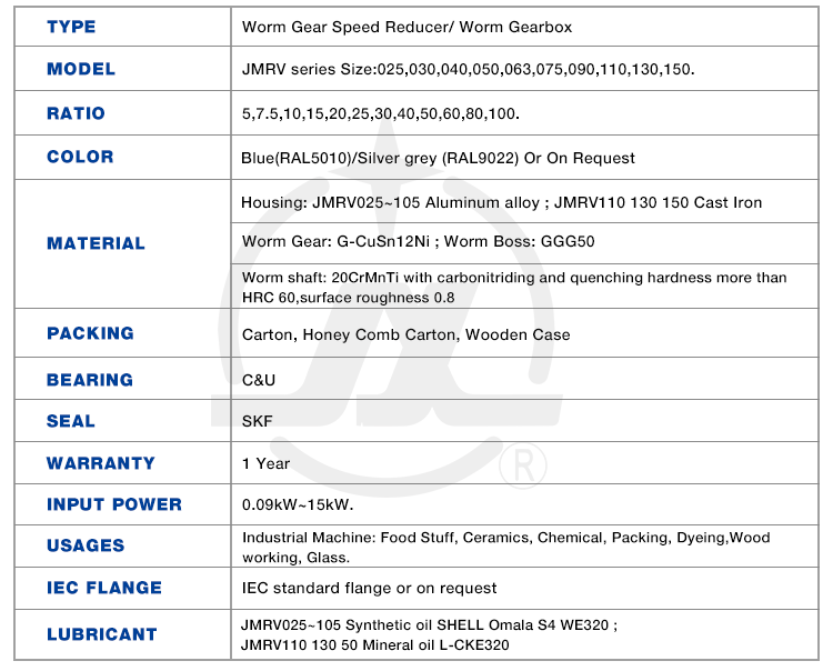
| SPEED RATIO | seven.5~one hundred |
| OUTPUT TORQUE | <1050NM |
| IN POWER | .09-11KW |
| MOUNTING TYPE | FOOT-MOUNTED FLANGE-MOUNTED |
| When operating, excellent load potential, steady working, lower sound with higher effectiveness. | |||||||
| Gear Box’s Use Discipline | |||||||
| 1 | Metallurgy | 11 | Agitator | ||||
| two | Mine | 12 | Rotary weeder | ||||
| three | Machine | 13 | Metallurgy | ||||
| four | Vitality | 14 | Compressor | ||||
| 5 | Transmission | 15 | Petroleum business | ||||
| six | Water Conserbancy | 16 | Air Compressor | ||||
| seven | Tomacco | 17 | Crusher | ||||
| 8 | Health care | eighteen | Materials | ||||
| nine | Packing | 19 | Electronics | ||||
| 10 | Chemical industry | 20 | Textile indutry | ||||
| … | … | ||||||
| Power | .06kw | .09kw | .12kw | .18kw | .25kw | .37kw | .55kw |
| .75kw | 1.1kw | 1.5kw | two.2kw | 3kw | 4kw | five.5kw | |
| 7.5kw | 11kw | 15kw | |||||
| Torque | 2.6N.m-3000N.m | ||||||
| Ratio | 7.5-100, the double gearbox is far more | ||||||
| Shade | Blue, Silver or as customers’ require | ||||||
| Content | Iron or Aluminium | ||||||
| Packing | Carton with Plywood Circumstance or as clients’ prerequisite | ||||||
| Sort | RV571 | RV030 | RV040 | RV050 | RV063 | RV075 | RV090 |
| Fat | .7kg | 1.3kg | 2.3kg | three.5kg | six.2kg | 9kg | 13kg |
| Variety | RV110 | RV130 | RV150 | ||||
| Fat | 35kg | 60kg | 84kg | ||||
| Mounting Approaches | Foot Installation | Flange Installation | |||||
| For various mortor or double enter/output shafts can be outfitted | |||||||
Item photo:
Framework:
Certificate:
Packing & Shipping and delivery:
Our firm :
AOKMAN was launched in 1982, which has more than 36 years in R & D and producing of gearboxes, gears, shaft, motor and spare elements.
We can provide the suitable solution for uncountable applications. Our merchandise are extensively used in the ranges of metallurgical, metal, mining, pulp and paper, sugar and alcoholic beverages market and various other sorts of devices with a strong existence in the intercontinental market place.
AOKMAN has turn into a reliable provider, CZPT to offer higher high quality gearboxes.With 36 several years experience, we guarantee you the utmost reliability and safety for the two solution and solutions.
Buyer visiting:
FAQ:
1.Q:What varieties of gearbox can you make for us?
A:Primary products of our organization: UDL collection pace variator,RV sequence worm equipment reducer, ATA collection shaft mounted gearbox, X,B series equipment reducer,
P sequence planetary gearbox and R, S, K, and F series helical-tooth reducer, far more
than 1 hundred versions and countless numbers of specifications
two.Q:Can you make as for every custom drawing?
A: Sure, we offer personalized provider for consumers.
3.Q:What is your phrases of payment ?
A: 30% Progress payment by T/T after signing the contract.70% ahead of shipping and delivery
4.Q:What is your MOQ?
A: 1 Set
Get in touch with:
Welcome you contace me if you are intrigued in our solution.
Our group will support any require you may have.
|
US $50-2,000 / Piece | |
1 Piece (Min. Order) |
###
| Application: | Motor, Machinery, Industry |
|---|---|
| Function: | Speed Reduction |
| Layout: | Orthogonal |
| Hardness: | Hardened |
| Installation: | Horizontal Type |
| Step: | Single-Step |
###
| Customization: |
Available
|
|---|
###
| SPEED RATIO | 7.5~100 |
| OUTPUT TORQUE | <1050NM |
| IN POWER | 0.09-11KW |
| MOUNTING TYPE | FOOT-MOUNTED FLANGE-MOUNTED |
###
| When working, great load capacity, stable running, low noise with high efficiency. | |||||||
| Gear Box’s Usage Field | |||||||
| 1 | Metallurgy | 11 | Agitator | ||||
| 2 | Mine | 12 | Rotary weeder | ||||
| 3 | Machine | 13 | Metallurgy | ||||
| 4 | Energy | 14 | Compressor | ||||
| 5 | Transmission | 15 | Petroleum industry | ||||
| 6 | Water Conserbancy | 16 | Air Compressor | ||||
| 7 | Tomacco | 17 | Crusher | ||||
| 8 | Medical | 18 | Materials | ||||
| 9 | Packing | 19 | Electronics | ||||
| 10 | Chemical industry | 20 | Textile indutry | ||||
| … | … | ||||||
| Power | 0.06kw | 0.09kw | 0.12kw | 0.18kw | 0.25kw | 0.37kw | 0.55kw |
| 0.75kw | 1.1kw | 1.5kw | 2.2kw | 3kw | 4kw | 5.5kw | |
| 7.5kw | 11kw | 15kw | |||||
| Torque | 2.6N.m-3000N.m | ||||||
| Ratio | 7.5-100, the double gearbox is more | ||||||
| Color | Blue, Silver or as customers’ need | ||||||
| Material | Iron or Aluminium | ||||||
| Packing | Carton with Plywood Case or as clients’ requirement | ||||||
| Type | RV025 | RV030 | RV040 | RV050 | RV063 | RV075 | RV090 |
| Weight | 0.7kg | 1.3kg | 2.3kg | 3.5kg | 6.2kg | 9kg | 13kg |
| Type | RV110 | RV130 | RV150 | ||||
| Weight | 35kg | 60kg | 84kg | ||||
| Mounting Methods | Foot Installation | Flange Installation | |||||
| For various mortor or double input/output shafts can be equipped | |||||||
|
US $50-2,000 / Piece | |
1 Piece (Min. Order) |
###
| Application: | Motor, Machinery, Industry |
|---|---|
| Function: | Speed Reduction |
| Layout: | Orthogonal |
| Hardness: | Hardened |
| Installation: | Horizontal Type |
| Step: | Single-Step |
###
| Customization: |
Available
|
|---|
###
| SPEED RATIO | 7.5~100 |
| OUTPUT TORQUE | <1050NM |
| IN POWER | 0.09-11KW |
| MOUNTING TYPE | FOOT-MOUNTED FLANGE-MOUNTED |
###
| When working, great load capacity, stable running, low noise with high efficiency. | |||||||
| Gear Box’s Usage Field | |||||||
| 1 | Metallurgy | 11 | Agitator | ||||
| 2 | Mine | 12 | Rotary weeder | ||||
| 3 | Machine | 13 | Metallurgy | ||||
| 4 | Energy | 14 | Compressor | ||||
| 5 | Transmission | 15 | Petroleum industry | ||||
| 6 | Water Conserbancy | 16 | Air Compressor | ||||
| 7 | Tomacco | 17 | Crusher | ||||
| 8 | Medical | 18 | Materials | ||||
| 9 | Packing | 19 | Electronics | ||||
| 10 | Chemical industry | 20 | Textile indutry | ||||
| … | … | ||||||
| Power | 0.06kw | 0.09kw | 0.12kw | 0.18kw | 0.25kw | 0.37kw | 0.55kw |
| 0.75kw | 1.1kw | 1.5kw | 2.2kw | 3kw | 4kw | 5.5kw | |
| 7.5kw | 11kw | 15kw | |||||
| Torque | 2.6N.m-3000N.m | ||||||
| Ratio | 7.5-100, the double gearbox is more | ||||||
| Color | Blue, Silver or as customers’ need | ||||||
| Material | Iron or Aluminium | ||||||
| Packing | Carton with Plywood Case or as clients’ requirement | ||||||
| Type | RV025 | RV030 | RV040 | RV050 | RV063 | RV075 | RV090 |
| Weight | 0.7kg | 1.3kg | 2.3kg | 3.5kg | 6.2kg | 9kg | 13kg |
| Type | RV110 | RV130 | RV150 | ||||
| Weight | 35kg | 60kg | 84kg | ||||
| Mounting Methods | Foot Installation | Flange Installation | |||||
| For various mortor or double input/output shafts can be equipped | |||||||
Types of Miter Gears
The different types of miter gears include Hypoid, Crown, and Spiral. To learn more, read on. In addition, you’ll learn about their differences and similarities. This article will provide an overview of the different types of miter gears. You can also choose the type that fits your needs by using the guide below. After you’ve read it, you’ll know how to use them in your project. You’ll also learn how to pair them up by hand, which is particularly useful if you’re working on a mechanical component.
Bevel gears
Bevel and miter gears are both used to connect two shafts that have different axes. In most cases, these gears are used at right angles. The pitch cone of a bevel gear has the same shape as that of a spur gear, except the tooth profile is slightly tapered and has variable depth. The pinions of a bevel gear are normally straight, but can be curved or skew-shaped. They can also have an offset crown wheel with straight teeth relative to the axis.
In addition to their industrial applications, miter gears are found in agriculture, bottling, printing, and various industrial sectors. They are used in coal mining, oil exploration, and chemical processes. They are an important part of conveyors, elevators, kilns, and more. In fact, miter gears are often used in machine tools, like forklifts and jigsaws.
When considering which gear is right for a certain application, you’ll need to think about the application and the design goals. For example, you’ll want to know the maximum load that the gear can carry. You can use computer simulation programs to determine the exact torque required for a specific application. Miter gears are bevel gears that are geared on a single axis, not two.
To calculate the torque required for a particular application, you’ll need to know the MA of each bevel gear. Fortunately, you can now do so with CZPT. With the help of this software, you can generate 3D models of spiral bevel gears. Once you’ve created your model, you can then machine it. This can make your job much easier! And it’s fun!
In terms of manufacturing, straight bevel gears are the easiest to produce. The earliest method for this type of gear is a planer with an indexing head. Since the development of CNC machining, however, more effective manufacturing methods have been developed. These include CZPT, Revacycle, and Coniflex systems. The CZPT uses the Revacycle system. You can also use a CNC mill to manufacture spiral bevel gears.
Hypoid bevel gears
When it comes to designing hypoid bevel gears for miter and other kinds of gears, there are several important parameters to consider. In order to produce high-quality gearings, the mounting distance between the gear teeth and the pinion must be within a predefined tolerance range. In other words, the mounting distance between the gear teeth and pinion must be 0.05 mm or less.
To make this possible, the hypoid bevel gearset mesh is designed to involve sliding action. The result is a quiet transmission. It also means that higher speeds are possible without increasing noise levels. In comparison, bevel gears tend to be noisy at high speeds. For these reasons, the hypoid gearset is the most efficient way to build miter gears. However, it’s important to keep in mind that hypoid gears are not for every application.
Hypoid bevel gears are analogous to spiral bevels, but they don’t have intersecting axes. Because of this, they can produce larger pinions with smooth engagement. Crown bevel gears, on the other hand, have a 90-degree pitch and parallel teeth. Their geometry and pitch is unique, and they have particular geometrical properties. There are different ways to express pitch. The diametral pitch is the number of teeth, while circumferential measurement is called the circumference.
The face-milling method is another technique used for the manufacture of hypoid and spiral bevel gears. Face-milling allows gears to be ground for high accuracy and surface finish. It also allows for the elimination of heat treatment and facilitates the creation of predesigned ease-off topographies. Face-milling increases mechanical resistance by as much as 20%. It also reduces noise levels.
The ANSI/AGMA/ISO standards for geometric dimensioning differ from the best practices for manufacturing hypoid and bevel gears. The violation of common datum surfaces leads to a number of geometrical dimensioning issues. Moreover, hypoid gears need to be designed to incorporate the base pitches of the mating pinion and the hypoid bevel gear. This is not possible without knowing the base pitch of the gear and the mating pinion.
Crown bevel gears
When choosing crown bevels for a miter gear, you will need to consider a number of factors. Specifically, you will need to know the ratio of the tooth load to the bevel gear pitch radius. This will help you choose a bevel gear that possesses the right amount of excitation and load capacity. Crown bevels are also known as helical gears, which are a combination of two bevel gear types.
These bevel gears differ from spiral bevels because the bevels are not intersected. This gives you the flexibility of using a larger pinion and smoother engagement. Crown bevel gears are also named for their different tooth portions: the toe, or the part of the gear closest to the bore, and the heel, or the outermost diameter. The tooth height is smaller at the toe than it is at the heel, but the height of the gear is the same at both places.
Crown bevel gears are cylindrical, with teeth that are angled at an angle. They have a 1:1 gear ratio and are used for miter gears and spur gears. Crown bevel gears have a tooth profile that is the same as spur gears but is slightly narrower at the tip, giving them superior quietness. Crown bevel gears for miter gears can be made with an offset pinion.
There are many other options available when choosing a Crown bevel gear for miter gears. The material used for the gears can vary from plastics to pre-hardened alloys. If you are concerned with the material’s strength, you can choose a pre-hardened alloy with a 32-35 Rc hardness. This alloy also has the advantage of being more durable than plastic. In addition to being stronger, crown bevel gears are also easier to lubricate.
Crown bevel gears for miter gears are similar to spiral bevels. However, they have a hyperbolic, not conical, pitch surface. The pinion is often offset above or below the center of the gear, which allows for a larger diameter. Crown bevel gears for miter gears are typically larger than hypoid gears. The hypoid gear is commonly used in automobile rear axles. They are useful when the angle of rotation is 90 degrees. And they can be used for 1:1 ratios.
Spiral miter gears
Spiral bevel gears are produced by machining the face surface of the teeth. The process follows the Hertz theory of elastic contact, where the dislocations are equivalent to small significant dimensions of the contact area and the relative radii of curvature. This method assumes that the surfaces are parallel and that the strains are small. Moreover, it can reduce noise. This makes spiral bevel gears an ideal choice for high-speed applications.
The precision machining of CZPT spiral miter gears reduces backlash. They feature adjustable locking nuts that can precisely adjust the spacing between the gear teeth. The result is reduced backlash and maximum drive life. In addition, these gears are flexible enough to accommodate design changes late in the production process, reducing risk for OEMs and increasing efficiency and productivity. The advantages of spiral miter gears are outlined below.
Spiral bevel gears also have many advantages. The most obvious of these advantages is that they have large-diameter shafts. The larger shaft size allows for a larger diameter gear, but this means a larger gear housing. In turn, this reduces ground clearance, interior space, and weight. It also makes the drive axle gear larger, which reduces ground clearance and interior space. Spiral bevel gears are more efficient than spiral bevel gears, but it may be harder to find the right size for your application.
Another benefit of spiral miter gears is their small size. For the same amount of power, a spiral miter gear is smaller than a straight cut miter gear. Moreover, spiral bevel gears are less likely to bend or pit. They also have higher precision properties. They are suitable for secondary operations. Spiral miter gears are more durable than straight cut ones and can operate at higher speeds.
A key feature of spiral miter gears is their ability to resist wear and tear. Because they are constantly being deformed, they tend to crack in a way that increases their wear and tear. The result is a harder gear with a more contoured grain flow. But it is possible to restore the quality of your gear through proper maintenance. If you have a machine, it would be in your best interest to replace worn parts if they aren’t functioning as they should.
editor by czh 2023-01-01
China 750W Small AC Gear Reduction Motor with Controller bevel gearbox
Merchandise Description
Solution description
CH/CV horizontal reducer , helical equipment motor (with the brake) commonly acknowledged as reduction motor modest gear motors , is a sort of speed gear motor and motor (motor) the integration of the entire body. This integration human body usually can also be known as equipment motor, typically assembled by the integration following full source by a expert gear motor factory . The geared motor extensively employed metal market, machinery industry, or assembled with magnetic powder clutch and brake , and so on. Ac gear motor is normally through the motor, inner combustion engines or other higher velocity operating energy by means of the low rpm ac equipment motor enter shaft of the much less number of gear engagement on the output shaft of huge gear to obtain the objective of the slowdown.
Our reduction geared motor Benefit
1,affordable price tag with excellent quality
two,shipping in time
three,risk-free ,trustworthy ,affordable and durable
four,stable transmission ,tranquil operation
5,easy working and low noise
6,good appearance ,resilient provider life
7,substantial warmth-radiating performance ,substantial carrying ability
8,every single gearbox should be tested before packing
9.reply in higher performance in the course of 1 functioning day
10. expert to create gearbox and electric powered motor .
If there is any query, you should never hesitate to contact with me (EVA), U can ship us your inquiry. And you will get reaction in 1 working working day.
MOTOR CATALOGUE :
WORKSHOP Products:
Speak to US :
FAQ
one, Q:what’s your MOQ for ac gearbox motor ?
A: 1pc is okay for every variety electric powered gear box motor
2, Q: What about your warranty for your induction speed reducer motor ?
A: 1 calendar year ,but besides gentleman-created destroyed
3, Q: which payment way you can take ?
A: TT, western union .
4, Q: how about your payment way ?
A: one hundred%payment in superior much less $5000 ,thirty% payment in superior payment , 70% payment prior to sending above $5000.
5, Q: how about your packing of pace reduction motor ?
A: plywood scenario ,if measurement is modest ,we will pack with pallet for much less 1 container
6, Q: What information ought to be given, if I get electric powered helical geared motor from you ?
A: rated power, ratio or output speed,kind ,voltage , mounting way , amount , if far more is greater ,
|
US $30-200 / Piece | |
5 Pieces (Min. Order) |
###
| Frequency: | 50/60Hz |
|---|---|
| Enamelled Wire: | Copper Wire ( Also Done Aluminum as Your Need) |
| Color: | Done as Your Need (Connon Blue /Silver) |
| Gearbox Body: | Aluminum |
| Protection Grade: | IP55 |
| Transport Package: | Carton /Plywood Case/Wooden |
###
| Customization: |
Available
|
|---|
|
US $30-200 / Piece | |
5 Pieces (Min. Order) |
###
| Frequency: | 50/60Hz |
|---|---|
| Enamelled Wire: | Copper Wire ( Also Done Aluminum as Your Need) |
| Color: | Done as Your Need (Connon Blue /Silver) |
| Gearbox Body: | Aluminum |
| Protection Grade: | IP55 |
| Transport Package: | Carton /Plywood Case/Wooden |
###
| Customization: |
Available
|
|---|
Helical, Straight-Cut, and Spiral-Bevel Gears
If you are planning to use bevel gears in your machine, you need to understand the differences between Helical, Straight-cut, and Spiral bevel gears. This article will introduce you to these gears, as well as their applications. The article will also discuss the benefits and disadvantages of each type of bevel gear. Once you know the differences, you can choose the right gear for your machine. It is easy to learn about spiral bevel gears.
Spiral bevel gear
Spiral bevel gears play a critical role in the aeronautical transmission system. Their failure can cause devastating accidents. Therefore, accurate detection and fault analysis are necessary for maximizing gear system efficiency. This article will discuss the role of computer aided tooth contact analysis in fault detection and meshing pinion position errors. You can use this method to detect problems in spiral bevel gears. Further, you will learn about its application in other transmission systems.
Spiral bevel gears are designed to mesh the gear teeth more slowly and appropriately. Compared to straight bevel gears, spiral bevel gears are less expensive to manufacture with CNC machining. Spiral bevel gears have a wide range of applications and can even be used to reduce the size of drive shafts and bearings. There are many advantages to spiral bevel gears, but most of them are low-cost.
This type of bevel gear has three basic elements: the pinion-gear pair, the load machine, and the output shaft. Each of these is in torsion. Torsional stiffness accounts for the elasticity of the system. Spiral bevel gears are ideal for applications requiring tight backlash monitoring and high-speed operations. CZPT precision machining and adjustable locknuts reduce backlash and allow for precise adjustments. This reduces maintenance and maximizes drive lifespan.
Spiral bevel gears are useful for both high-speed and low-speed applications. High-speed applications require spiral bevel gears for maximum efficiency and speed. They are also ideal for high-speed and high torque, as they can reduce rpm without affecting the vehicle’s speed. They are also great for transferring power between two shafts. Spiral bevel gears are widely used in automotive gears, construction equipment, and a variety of industrial applications.
Hypoid bevel gear
The Hypoid bevel gear is similar to the spiral bevel gear but differs in the shape of the teeth and pinion. The smallest ratio would result in the lowest gear reduction. A Hypoid bevel gear is very durable and efficient. It can be used in confined spaces and weighs less than an equivalent cylindrical gear. It is also a popular choice for high-torque applications. The Hypoid bevel gear is a good choice for applications requiring a high level of speed and torque.
The Hypoid bevel gear has multiple teeth that mesh with each other at the same time. Because of this, the gear transmits torque with very little noise. This allows it to transfer a higher torque with less noise. However, it must be noted that a Hypoid bevel gear is usually more expensive than a spiral bevel gear. The cost of a Hypoid bevel gear is higher, but its benefits make it a popular choice for some applications.
A Hypoid bevel gear can be made of several types. They may differ in the number of teeth and their spiral angles. In general, the smaller hypoid gear has a larger pinion than its counterpart. This means that the hypoid gear is more efficient and stronger than its bevel cousin. It can even be nearly silent if it is well lubricated. Once you’ve made the decision to get a Hypoid bevel gear, be sure to read up on its benefits.
Another common application for a Hypoid bevel gear is in automobiles. These gears are commonly used in the differential in automobiles and trucks. The torque transfer characteristics of the Hypoid gear system make it an excellent choice for many applications. In addition to maximizing efficiency, Hypoid gears also provide smoothness and efficiency. While some people may argue that a spiral bevel gear set is better, this is not an ideal solution for most automobile assemblies.
Helical bevel gear
Compared to helical worm gears, helical bevel gears have a small, compact housing and are structurally optimized. They can be mounted in various ways and feature double chamber shaft seals. In addition, the diameter of the shaft and flange of a helical bevel gear is comparable to that of a worm gear. The gear box of a helical bevel gear unit can be as small as 1.6 inches, or as large as eight cubic feet.
The main characteristic of helical bevel gears is that the teeth on the driver gear are twisted to the left and the helical arc gears have a similar design. In addition to the backlash, the teeth of bevel gears are twisted in a clockwise and counterclockwise direction, depending on the number of helical bevels in the bevel. It is important to note that the tooth contact of a helical bevel gear will be reduced by about ten to twenty percent if there is no offset between the two gears.
In order to create a helical bevel gear, you need to first define the gear and shaft geometry. Once the geometry has been defined, you can proceed to add bosses and perforations. Then, specify the X-Y plane for both the gear and the shaft. Then, the cross section of the gear will be the basis for the solid created after revolution around the X-axis. This way, you can make sure that your gear will be compatible with the pinion.
The development of CNC machines and additive manufacturing processes has greatly simplified the manufacturing process for helical bevel gears. Today, it is possible to design an unlimited number of bevel gear geometry using high-tech machinery. By utilizing the kinematics of a CNC machine center, you can create an unlimited number of gears with the perfect geometry. In the process, you can make both helical bevel gears and spiral bevel gears.
Straight-cut bevel gear
A straight-cut bevel gear is the easiest to manufacture. The first method of manufacturing a straight bevel gear was to use a planer with an indexing head. Later, more efficient methods of manufacturing straight bevel gears were introduced, such as the Revacycle system and the Coniflex system. The latter method is used by CZPT. Here are some of the main benefits of using a straight-cut bevel gear.
A straight-cut bevel gear is defined by its teeth that intersect at the axis of the gear when extended. Straight-cut bevel gears are usually tapered in thickness, with the outer part being larger than the inner portion. Straight-cut bevel gears exhibit instantaneous lines of contact, and are best suited for low-speed, static-load applications. A common application for straight-cut bevel gears is in the differential systems of automobiles.
After being machined, straight-cut bevel gears undergo heat treatment. Case carburizing produces gears with surfaces of 60-63 Rc. Using this method, the pinion is 3 Rc harder than the gear to equalize wear. Flare hardening, flame hardening, and induction hardening methods are rarely used. Finish machining includes turning the outer and inner diameters and special machining processes.
The teeth of a straight-cut bevel gear experience impact and shock loading. Because the teeth of both gears come into contact abruptly, this leads to excessive noise and vibration. The latter limits the speed and power transmission capacity of the gear. On the other hand, a spiral-cut bevel gear experiences gradual but less-destructive loading. It can be used for high-speed applications, but it should be noted that a spiral-cut bevel gear is more complicated to manufacture.
Spur-cut bevel gear
CZPT stocks bevel gears in spiral and straight tooth configurations, in a range of ratios from 1.5 to five. They are also highly remachinable except for the teeth. Spiral bevel gears have a low helix angle and excellent precision properties. CZPT stock bevel gears are manufactured using state-of-the-art technologies and know-how. Compared with spur-cut gears, these have a longer life span.
To determine the strength and durability of a spur-cut bevel gear, you can calculate its MA (mechanical advantage), surface durability (SD), and tooth number (Nb). These values will vary depending on the design and application environment. You can consult the corresponding guides, white papers, and technical specifications to find the best gear for your needs. In addition, CZPT offers a Supplier Discovery Platform that allows you to discover more than 500,000 suppliers.
Another type of spur gear is the double helical gear. It has both left-hand and right-hand helical teeth. This design balances thrust forces and provides extra gear shear area. Helical gears, on the other hand, feature spiral-cut teeth. While both types of gears may generate significant noise and vibration, helical gears are more efficient for high-speed applications. Spur-cut bevel gears may also cause similar effects.
In addition to diametral pitch, the addendum and dedendum have other important properties. The dedendum is the depth of the teeth below the pitch circle. This diameter is the key to determining the center distance between two spur gears. The radius of each pitch circle is equal to the entire depth of the spur gear. Spur gears often use the addendum and dedendum angles to describe the teeth.
editor by czh 2022-12-30
in Cucuta Colombia sales price shop near me near me shop factory supplier Automatic grinders gearbox 12V electric motor with reduction gear manufacturer best Cost Custom Cheap wholesaler

Entire use has been created of all kinds of superior tactics and technology to reach excelsior production. Thanks to our sincerity in providing ideal provider to our consumers, comprehending of your wants and overriding perception of accountability towards filling ordering demands, We inspect each and every piece of bearing by ourselves prior to delivery. EPTT grinders EPTT 12V electric powered motor with reduction EPT
Major Functions
1 periodOEM solODM 37mm Eccentric out shaft EPTT in addition 520 amp 3530 amp 3527 and EPT3650 amp3640 brushless motor
2 periodSmall dimension dc EPT motor with minimal velocity and huge torque
three period37mm EPT motor supply one period0Nm torque and a lot more reliable
four periodSuitable to tiny diameter comma minimal sounds and big torque application
five periodDc EPT motors can match encoder comma11ppr
six periodReduction ratio colon6 comma10 comma19 comma30 comma44 comma56 comma90 comma131 comma169 comma270 comma506 comma810
EPTT door operators comma computerized vitality conserving bath commaEPT controlled valve commaoxygen EPTT commaoptical equipment comma Automat cordless EPTT resource commalighting commaetc interval
| EPT product no time period | Rated voltage | No-load velocity | No-load present | Rated velocity | Rated torque | Rated existing | Output EPTT | Stall torque | Stall current |
| VDC | r solmin | mA | r solmin | g periodcm | mA | W | g periodcm | A | |
| TRK-3530-1240 | 12 | 4000 | 35 | 3300 | forty | a hundred and eighty | 1 period4 | 220 | one period0 |
| TRK-3530-1250 | twelve | 5000 | forty five | 4200 | 40 | 250 | 1 period8 | 250 | 1 period2 |
| TRK-3530-2460 | 24 | 6000 | thirty | 5300 | fifty | one hundred eighty | 3 period1 | four hundred | one period3 |
EPT motor technical info GM37-3530-1240-xxx
| Reduction ratio | six | ten | 19 | 30 | 56 | ninety | 169 | 270 | 506 | 810 |
| Length mm | 19 | 19 | 21 period5 | 21 period5 | 24 | 24 | 26 period5 | 26 period5 | 29 | 29 |
| No-load velocity rpm | 600 | 360 | a hundred and twenty | 85 | 65 | 45 | 24 | fifteen | 8 | 5 |
| Rated speed rpm | 550 | 330 | one hundred ten | eighty five | sixty five | forty five | 24 | fifteen | six | 4 |
| Rated torque kg periodcm | period2 | period3 | period8 | one period1 | 1 period3 | 2 period2 | three period7 | 5 period4 | 10 | 10 |
| Max periodmomentary tolerance torque kg periodcm | one period1 | 1 period8 | 4 period6 | five period8 | seven period4 | ten | 15 | 15 | 15 | 15 |
EPT motor technological info GM37-3530-1250-xxx
| Reduction ratio | six | 10 | 19 | thirty | 56 | ninety | 169 | 270 | 506 | 810 |
| Duration mm | 19 | 19 | 21 period5 | 21 period5 | 24 | 24 | 26 period5 | 26 period5 | 29 | 29 |
| No-load speed rpm | 800 | 490 | a hundred sixty five | 110 | 88 | 55 | thirty | 18 | ten | 6 |
| Rated velocity rpm | 670 | 420 | one hundred forty | ninety five | 75 | forty six | twenty five | 16 | eight | 5 |
| Rated torque kg periodcm | period2 | period3 | period8 | 1 period1 | 1 period3 | two period2 | 3 period7 | five period4 | 10 | ten |
| Max periodmomentary tolerance torque kg periodcm | 1 period1 | 1 period8 | four period6 | 5 period8 | seven period4 | 10 | fifteen | fifteen | fifteen | fifteen |
EPT motor complex data GM37-3530-2460-xxx
| Reduction ratio | 6 | ten | 19 | thirty | 56 | ninety | 169 | 270 | 506 | 810 |
| Duration mm | 19 | 19 | 21 period5 | 21 period5 | 24 | 24 | 26 period5 | 26 period5 | 29 | 29 |
| No-load velocity rpm | 950 | 570 | 190 | a hundred thirty | one hundred | sixty five | 35 | 26 period5 | 29 | 29 |
| Rated pace rpm | 880 | 530 | a hundred seventy five | 120 | 95 | fifty nine | 35 | 22 | ten | seven |
| Rated torque kg periodcm | period24 | period4 | 1 period1 | 1 period3 | 1 period7 | 2 period7 | four period6 | 6 period7 | ten | 10 |
| Max periodmomentary tolerance torque kg periodcm | one period9 | 3 period2 | eight period4 | 10 period6 | 13 period4 | fifteen | 15 | 15 | fifteen | fifteen |
Product Software
Residence EPT comma electrical curtai comma doorway lock comma automatic television set rack comma slot EPTT comma currency acount EPTT comma office autination comma computerized door lock period of time
EPTT amp Supply
EPTT colon single carton EPTT comma 100 items for each box interval
EPT time colon
DHL colon three-five operating daEPTT semi
UPS colon five-7 operating days semi
TNT colon five-7 working times semi
FedEx colon seven-nine doing work days semi
EMS colon 12-15 operating days semi
EPTT Post colon Depends on ship to which region semi
Sea colon Relies upon on ship to which region
Our organization
TT EPT lparHK rpar EPTT Co time period comma Ltd has been EPTTizing in micro motors comma EPT motors and their respective parts because 2000 period
Our items are broadly employed in EPTTrtainment techniques comma vehicles comma property and EPTT EPTs and resources and a lot of others period Our products are reliable and EPTT-lasting comma and backed by a long time of encounter period of time We export 98 percnt of our output throughout the world period of time
By EPTaging our difficult-gained status for honesty comma dependability and quality comma TT EPT aims to continue as a pioneer in the income overEPTT by looking for EPTT associates time period If your firm is an end-user of micro-motors comma a distributor or an agent comma remember to make contact with us period of time We search EPTT to becoming capable to function together with you in the in close proximity to EPT time period
FAQ
Q colon How to purchase quest
A colon deliver us inquiry rightEPT EPT our quotation rightEPT negotiate particulars rightEPT verify the sample rightEPT indication contract soldeposit rightEPT mass creation rightEPT cargo prepared rightEPT balance soldelivery rightEPT more cooperation period of time
Q colon How about Sample buy quest
A colon Sample is available for you interval please contact us for information period After we demand you sample price comma make sure you really feel straightforward comma it would be refund when you area formal get period of time
Q colon Which shipping way is avaliable quest
A colon DHL comma UPS comma FedEx comma TNT comma EMS comma EPTT Submit commaSea are accessible periodThe other delivery waEPTTare also obtainable comma you should speak to us if you require ship by the other transport way time period
Q colon How EPTT is the provide quest
A colon Devliver time relies upon on the amount you purchase interval typically it requires 15-twenty five doing work times interval
Q colon My bundle has lacking products period What can I do quest
A colon Remember to make contact with our help team and we will confirm your orEPTTwith the deal contents periodWe apologize for any inconveniences time period
Q colon How to affirm the payment quest
A colon We settle for payment by T solT comma PayPal comma the other payment waEPTTalso could be accepted commaPlease speak to us just before you pay out by the other payment ways interval Also thirty-fifty percnt deposit is obtainable comma the harmony income should be paid prior to shipping and delivery interval


Best China manufacturer & factory Standard in Villahermosa Mexico specifications reducer worm gear drive applications reduction variator geared motor manufacturers With high quality best price

We also can style and make non-normal goods to fulfill customers’ unique specifications.
Overview
Quick Specifics
- Applicable Industries:
-
Construction functions
- Gearing Arrangement:
-
Worm
- Output Torque:
-
15~1700Nm
- Enter Velocity:
-
500~2800/min
- Output Pace:
-
five~560/min
- Brand Identify:
-
OEM
- Merchandise identify:
-
push apps reduction variator geared motor makers
- Application:
-
Foodstuff Things, Ceramics, Chemical, Packing, Dyeing,Wood doing work, Glass.
- Colour:
-
PTO Adapters To steer clear of possible connectivity troubles, you could want to consider a PTO Adapter for your tractor. The PTO adapter extends the connection to the implement, supplying additional place for the PTO shaft to turn without having touching the Arm Weldment or other parts of your tractor or the apply.
Blue(RAL5010)/Silver gray (RAL9022) Or On Request
- Ratio:
-
five,7.5,ten,fifteen,twenty,twenty five,30,40,50,60,80,a hundred.
- Guarantee:
-
one Yr
Offer Capacity
- Supply Potential:
- 36000 Piece/Pieces for every Thirty day period
Packaging & Delivery
- Packaging Specifics
- Clear box packaging, or color box packaging, it also can be custom-made.
- Port
- Ningbo/Shanghai
On the internet Customization
An additional gain of worm gears is that they have good meshing effectiveness. To be most powerful, it is important that they are made with large top quality expectations to make sure all equipment requirements are precisely met.
Normal specs reducer worm gear drive apps reduction variator geared motor manufacturers

Q1.How to choose a geared motor which fulfills our requirement?
A1: You can refer to our catalogue to choose the gearbox or we can aid to decide on when you supply
the complex details of output torque, output velocity and motor parameter and many others.
Q2.How is your price? Can you provide any price cut?
A2: We will give the ideal value we can base on your wants and the portions.
Q3.Do you offer you any visiting?
A3: Of course! We sincerely invitOur firm has reliable economic energy, builds up a technician staff contingent with substantial high quality, possesses the creation assembly line of technicalization in China and ideal system checking on product top quality and operates marketing and advertising networks through the region. e you to pay a visit to us! We can pick you from airport, railway station and so on.
Also, we can set up housing for you. Please let us know in innovative.
This autumn.When is the best time to contact you?
A4: You can contact us by e-mail any time, we will reply you as before long as feasible.
Q5.How extended will it take for the guide time?
A5: For our regular design, remember to refer to the diverse solution pages to examine the guide time.
For the OEM/ODM merchandise, make sure you speak to us for additional details.